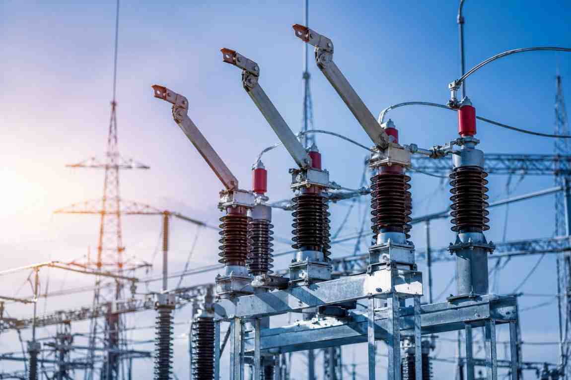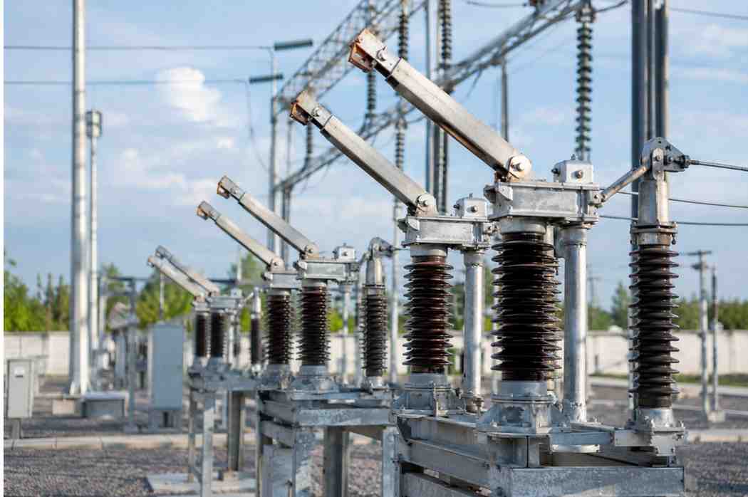
Walk into any 33 kV substation in India and you will find electrical isolators doing one of the most critical jobs in the entire system: creating a visible, confirmed break in the circuit before any maintenance work begins. No confirmation of isolation, no work permit. That is the rule across every utility and industrial plant that takes safety seriously.
Yet isolator-related accidents still happen. Not because the product failed, but because the installation was done incorrectly, the specifications were mismatched, or the commissioning checks were skipped under project pressure.
This guide covers Electrical Isolator Installation in India from the ground up, so that engineers, EPC teams, and industrial buyers can approach every isolator installation with the technical confidence it deserves.
Step 1: Understand What You Are Installing and Why It Matters
Before a single bolt is tightened, the installation team needs to understand what an electrical isolator does and what it does not do.
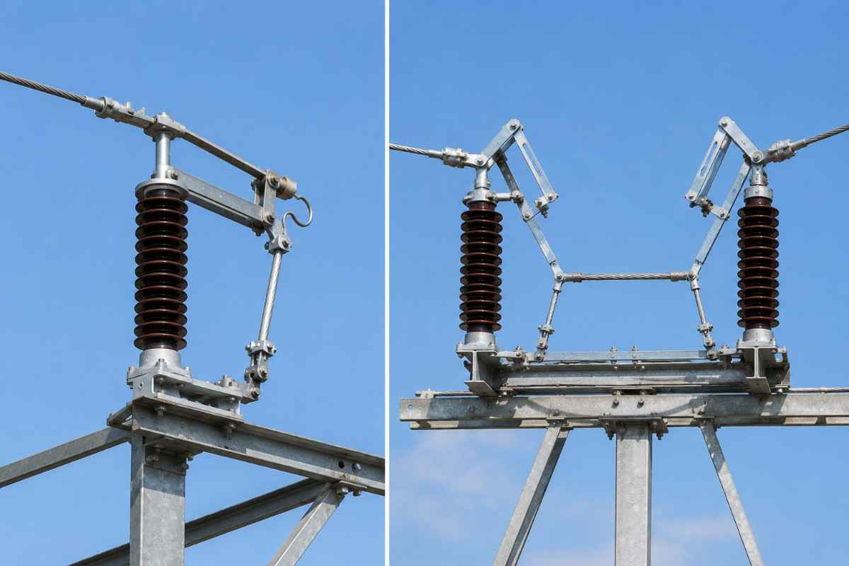
An isolator is a mechanical switching device used to open or close a circuit under no-load or negligible-load conditions. It creates a visible gap in the circuit that confirms de-energization before maintenance personnel enter a bay or work on equipment.
It is not a fault-interrupting device. It cannot open a live, loaded circuit. Attempting to do so causes severe arcing, equipment damage, and in many cases, fatal accidents.
This is the single most important fact every site engineer must communicate to every installation crew member before work begins.
Step 2: Verify the Design Specifications Against Site Conditions
One of the most common reasons isolator installations fail in service is specification mismatch. The isolator was rated correctly for voltage class but wrong for the actual site conditions.
Before procurement or installation begins, confirm the following:
Voltage Class Match the rated voltage to the system voltage class. Common classes in Indian installations are 11 kV, 33 kV, 66 kV, 110 kV, and 220 kV. Always specify the highest system voltage, not the nominal voltage, to ensure adequate insulation margin.
Continuous Current Rating The isolator must carry the maximum continuous load current of the circuit without overheating. Add a minimum 20 percent safety margin above the calculated maximum load current when selecting the rating.
Short Circuit Withstand Current The isolator must survive the mechanical and thermal stress of a fault current until the upstream protection clears it. This requires knowing the prospective short circuit level at the installation point. Undersizing this parameter is a common and dangerous error.
Creepage Distance and Pollution Level India has widely varying pollution environments. Coastal substations, industrial areas, cement plants, and agricultural zones all face different contamination levels. The pollution level (light, medium, heavy, or very heavy per IEC 60815) determines the required insulator creepage distance. Specifying standard creepage in a heavy-pollution environment leads to insulator flashovers within one monsoon season.
Mounting Configuration Isolators come in single-break, double-break, and centre-break configurations with vertical or horizontal operating planes. The mounting configuration must suit the substation bay layout, available clearances, and the number of phases being isolated.
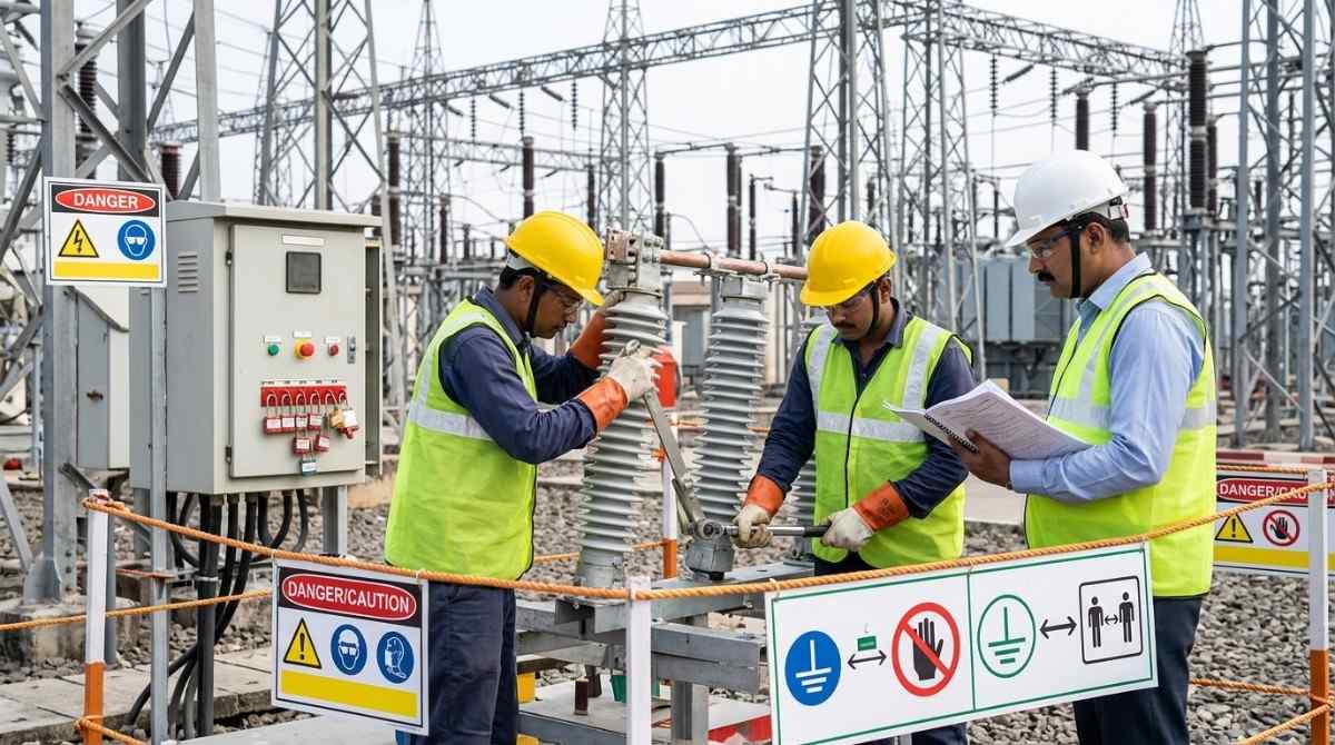
Step 3: Inspect the Equipment Before Installation Begins
Every isolator arriving on site should go through a receiving inspection before it is taken to the bay. This is a step that gets skipped under tight project schedules and then costs the project dearly later.
Receiving inspection should cover:
- Physical condition of insulators (cracks, chips, or impact marks from transit)
- Contact blade condition (no deformation, scoring, or surface contamination)
- Operating mechanism integrity (no bent linkages, loose bolts, or damaged spring assemblies)
- Nameplate data verification (check rated voltage, current, and short circuit rating against the purchase order)
- Dimensional check against the approved drawing (phase-to-phase spacing, mounting bolt pattern, overall height)
If any item fails inspection, it should be tagged, quarantined, and reported before installation proceeds. Installing a damaged isolator and discovering the problem after commissioning is far more expensive than replacing it before erection.
Step 4: Prepare the Support Structure Correctly
The structural foundation of an isolator installation is often treated as a civil contractor's problem. It should not be. Structural inadequacy is a direct cause of isolator misalignment, contact pressure loss, and mechanical failure in service.
Key requirements for the support structure:
- The base frame must be fabricated from hot-dip galvanized steel as per IS 2629, not just painted mild steel
- All anchor bolts must be embedded at the correct depth and spacing as per the manufacturer's approved drawing
- The mounting surface must be level within the tolerances specified by the manufacturer (typically within 2 mm across the base frame)
- The structure must be designed to handle the mechanical loads from the isolator operating mechanism, ice loading (in northern zones), and wind loading per IS 875
A structure that is 5 degrees out of level causes blade misalignment that prevents proper contact engagement. This results in high contact resistance, hotspot formation, and eventual contact failure under load.
Step 5: Erect the Isolator and Align the Contacts
This is the most technically demanding part of the installation. It requires a qualified electrical erection crew following the manufacturer's installation manual precisely.
Phase Assembly
Assemble the three phase units on the base structure according to the layout drawing. Maintain correct phase-to-phase spacing as per the voltage class clearance requirements of IS 5082 and the applicable substation design standard.
Insulator Stack Alignment
Each insulator column must be vertical and in line with the phase axis. Misaligned insulator stacks create mechanical bending stress on the insulator sheds that leads to insulator cracking over time, especially in wind-exposed outdoor substations.
Contact Blade Alignment
When the isolator is driven to the closed position manually, the moving blade must enter the fixed contact with correct alignment and sufficient contact force. The manufacturer specifies the acceptable contact force range. Measure it with a contact pressure gauge and record the readings.
Insufficient contact pressure means the contact interface resistance is too high. Under full load current, this causes localized heating, surface oxidation, and a progressively worsening contact that eventually welds or fails open during operation.
Operating Mechanism Linkage
Connect the operating rod linkages between the mechanism box and each phase unit. Drive the mechanism through several open-close cycles by hand to verify that all three phases operate simultaneously and reach their correct end positions without binding or excessive resistance.
Step 6: Commission the Earthing Switch (If Applicable)
Many isolators in Indian substations are supplied with an integral earthing switch. This provides a reliable grounded path before maintenance personnel enter the bay. The installation and commissioning of the earthing switch follows the same alignment and contact pressure checks as the main isolator blade.
Additionally, confirm that the mechanical interlock between the main isolator and the earthing switch is functioning correctly. The interlock must physically prevent the earthing switch from closing unless the main isolator is fully open, and must prevent the main isolator from closing while the earthing switch is closed. This is not optional. It is a fundamental safety requirement.
Step 7: Perform Pre-Commissioning Electrical Tests
Once mechanical installation and alignment are complete, the isolator must pass a series of electrical tests before being energized.
| Test | Purpose | Acceptable Limit |
|---|---|---|
| Contact Resistance (micro-ohm) | Confirms good contact engagement | Per manufacturer spec, typically below 100 micro-ohm |
| Insulation Resistance (Mega-ohm) | Checks insulator integrity | Minimum 1000 Mega-ohm at 5 kV DC |
| High Voltage Withstand (Power Frequency) | Confirms insulation quality | As per IS 9921 or applicable standard |
| Mechanical Operations Test | Verifies correct travel and end positions | Minimum 5 open-close cycles without binding |
| Interlock Functional Test | Confirms earthing switch interlock logic | Pass or fail, no partial acceptance |
All test results must be recorded in the commissioning test report and retained as part of the project documentation. For utility projects in India, these records are mandatory for energization approvals.
Step 8: Common Installation Mistakes That Lead to Field Failures
Understanding where installations go wrong helps every engineer avoid repeating the same errors.
Mistake 1: Lubricating contacts with the wrong grease
Contact surfaces must be treated with the specific contact grease recommended by the manufacturer. Using ordinary petroleum-based grease on silver-plated contacts causes rapid oxidation and contact resistance increase. This mistake is extremely common on Indian construction sites where contractors substitute unavailable materials with what is locally accessible.
Mistake 2: Over-torquing insulator mounting bolts
Porcelain and polymer insulators have specific torque limits for their mounting flanges. Exceeding these during installation cracks the insulator internally. The crack may not be visible externally but causes flashover during the first high-humidity monsoon event.
Mistake 3: Skipping phase synchronization checks on gang-operated isolators
In a three-phase gang-operated unit, the three blades must open and close at exactly the same mechanical position. If one phase lags behind, it may not fully engage its contact even when the mechanism registers the closed position. This is checked by marking the blade travel angles on each phase and comparing them.
Mistake 4: Installing without verifying system earth continuity
The isolator frame, base structure, and mechanism box must all be bonded to the station earth grid. An unbonded isolator frame is a shock hazard. Verify earth continuity from each isolator frame to the main earth grid with a low-resistance measurement before energization.
How SPKN India Supports Safe Electrical Isolator Installation in India
Getting the product right is only one part of the equation. SPKN India understands that the other part is what happens between factory delivery and first energization.
SPKN India manufactures isolators conforming to IS 9921 and IEC 62271-102 across voltage classes from 11 kV to 220 kV, in single-break, double-break, and vertical-break configurations. Products are available with and without integral earthing switches, in both polymer and porcelain insulated versions, for manual and motorized gang-operated applications.
What sets SPKN India apart for EPC contractors and site engineers is the level of technical documentation supplied with every product. Installation manuals include torque specifications, contact pressure limits, lubrication material specifications, and step-by-step alignment procedures written for actual field conditions in India, not generic international templates.
For large substation packages, SPKN India offers pre-delivery dimensional verification, factory acceptance testing with customer witness, and post-delivery technical support during erection and commissioning.
Procurement managers working with SPKN India also benefit from consistent supply of type-test-certified products, which streamlines the utility approval process and avoids the last-minute documentation scrambles that delay energization milestones.
Conclusion
Safe Electrical Isolator Installation in India is not achieved by using an expensive product alone. It is the result of correct specification, disciplined site inspection, accurate mechanical alignment, verified electrical performance, and proper documentation at every stage.
The steps covered in this guide represent the standard that every isolator installation in India should meet, whether it is a 220 kV transmission bay or an 11 kV industrial feeder. Cutting corners at any of these stages creates risks that show up at the worst possible time, typically under monsoon loading conditions or during a system fault event.
SPKN India provides the products and technical support to help you meet that standard. Share your project specifications with the SPKN India team and get the right guidance from engineers who understand Indian substation construction from the field up.