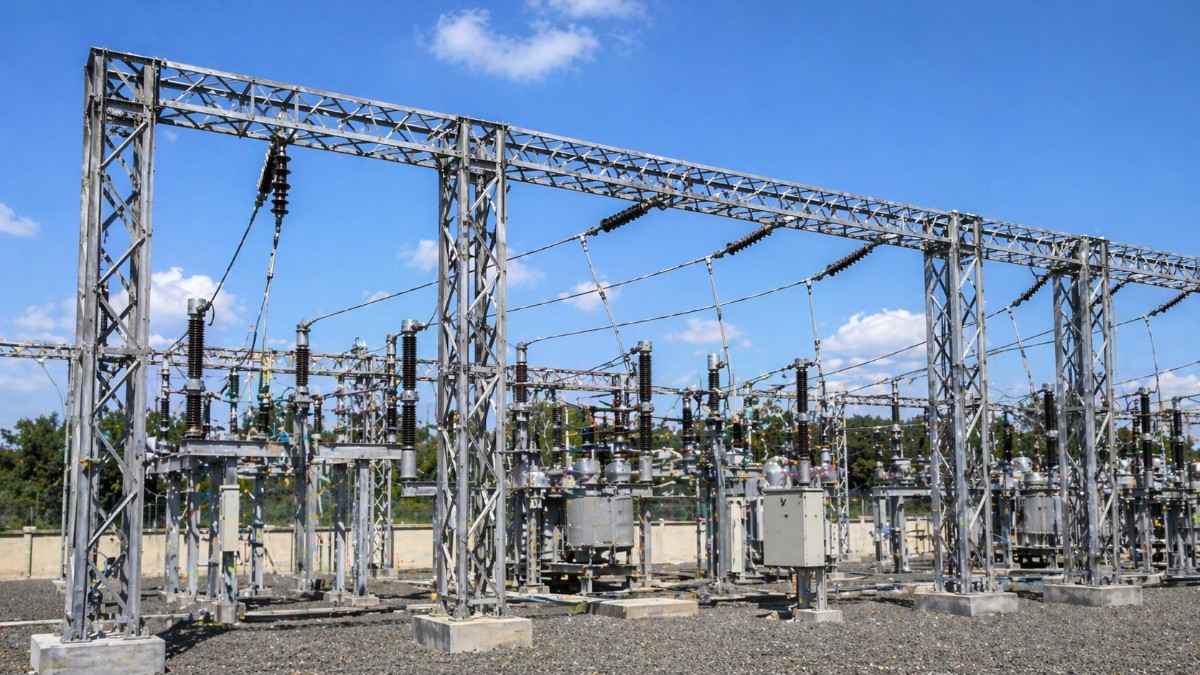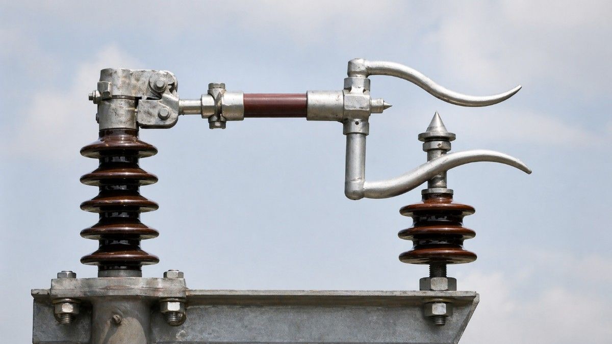
Walk into any outdoor substation in India and look up at the overhead lines coming in. Chances are, you will spot a V-shaped or diverging metal horn mounted near the insulators. That is a horn gap lightning arrester, and it has been quietly protecting power systems for decades.
Most electrical engineers know it exists. But very few can explain exactly what each part does, why it is shaped the way it is, and what happens inside it during an actual lightning strike.
That lack of understanding leads to poor selection, wrong installation, and premature failure, all of which cost power utilities and industries heavily.
This blog breaks down the 7 key parts of a horn gap lightning arrester in a way that is easy to understand, technically accurate, and practically useful, whether you are an electrical engineer, a procurement manager, or an EPC contractor working on a substation project in India.
What Is a Horn Gap Lightning Arrester and Why Does It Still Matter?
A horn gap lightning arrester is one of the oldest and most robust forms of overvoltage protection used in power systems. It works on a beautifully simple principle: when a high-voltage surge arrives, it jumps across a gap between two diverging electrodes shaped like horns. The arc that forms rises upward due to heat and electromagnetic forces, stretches, and eventually extinguishes itself.
No complex electronics. No moving parts under normal operation. Just physics doing its job.
In India, horn gap lightning arresters are widely used in:
- 11kV and 33kV distribution substations
- Rural electrification networks
- Transmission line protection at tower bases
- Industrial feeder protection
- Railway traction substations
They are rugged, low-maintenance, and cost-effective for outdoor installations where simplicity and reliability matter more than precision clamping. Understanding its parts helps you select the right one, install it correctly, and maintain it better.
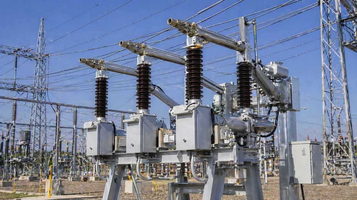
Part 1: The Lower Horn Electrode (Fixed Electrode)
This is the starting point of the arc. The lower horn electrode is a thick metal rod, typically made of copper or copper alloy, fixed at the base of the arrester assembly.
When a lightning surge or switching overvoltage arrives on the line, the voltage difference between the two horn electrodes becomes high enough to ionize the air in the gap. The arc initiates right here, at the narrowest point between the two horns.
The lower electrode is connected to the live conductor or the line terminal. Its shape, diameter, and material directly affect how cleanly the arc initiates and how long the electrode lasts before it needs replacement.
In Indian substations operating at 11kV and 33kV, the lower electrode is typically made from high-conductivity copper to handle repeated arc events without significant erosion.
Part 2: The Upper Horn Electrode (Moving Arc Electrode)
The upper horn electrode is the other half of the gap and it is shaped to diverge outward and upward from the lower electrode. This diverging shape is the key to the entire arc extinction mechanism.
When the arc forms at the base of the gap, the heat it generates causes the surrounding air to expand rapidly. This hot air rises, and it carries the arc upward along the diverging horns. As the arc travels up the horns, the gap length increases progressively. A longer gap means higher arc resistance, which reduces the arc current until it can no longer sustain itself and extinguishes.
This is what makes the horn gap design so elegant. The geometry of the upper electrode does the work of arc extinction without any external mechanism.
The upper electrode is connected to the earth side of the circuit, ensuring that the surge energy is safely diverted to ground once the arc path is established.
Part 3: The Series Gap (Air Gap Between the Horns)
The air gap between the two horn electrodes is not just empty space. It is the most critical parameter of the entire arrester.
The gap distance is precisely calibrated to:
- Spark over at the correct overvoltage level (the sparkover voltage)
- Not spark over during normal operating voltage fluctuations
- Allow clean arc initiation without pre-strike at lower voltages
For a standard 11kV horn gap lightning arrester used in Indian distribution systems, the gap is set to spark over at approximately 75kV to 80kV peak. For 33kV systems, the sparkover voltage is set higher accordingly.
If the gap is too small, the arrester will spark over unnecessarily during normal voltage swings, causing nuisance tripping and electrode erosion. If it is too large, it will not operate during genuine overvoltage events and offer no protection at all.
Gap setting is one of the most common causes of horn gap arrester failure in the field. Always verify gap distance during installation and after any arc event.
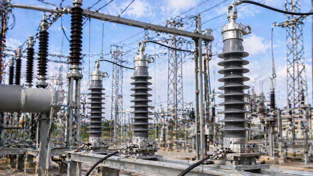
Part 4: The Support Insulators (Mounting Insulators)
The horn electrodes do not float in the air on their own. They are mounted on support insulators that serve two critical functions: mechanical support and electrical isolation.
The insulators hold the electrodes at the precise gap distance and angle while keeping them electrically isolated from the grounded supporting structure.
In India, horn gap lightning arresters typically use:
- Porcelain pin insulators for standard outdoor installations
- Polymer insulators for installations in highly polluted or coastal areas where porcelain is prone to surface tracking
The insulator material and creepage distance must be selected based on the pollution level of the installation site. A substation near a coastal area in Tamil Nadu or an industrial zone in Gujarat will require insulators with much higher creepage distance compared to a clean rural substation in Madhya Pradesh.
Insulator failure is one of the leading causes of horn gap arrester malfunction in India, particularly in areas with high airborne pollutants, salt deposits, or cement dust.
Part 5: The Grounding Terminal and Earth Connection
The grounding terminal is where the surge energy ultimately exits the system. It is the earthing connection point of the horn gap lightning arrester, typically located at the base of the arrester assembly.
This terminal must be connected to a low-resistance earth electrode system. If the earth resistance is high, the surge voltage cannot be effectively diverted. Instead, it will back-feed into the system and cause exactly the kind of damage the arrester was meant to prevent.
For horn gap lightning arresters installed in Indian substations, the earth resistance at the grounding terminal should ideally be below 5 ohms, as per IS 3043 guidelines.
A proper earth connection also prevents the arc from re-striking after extinction. If the earth path has high impedance, the recovery voltage can cause the arc to reignite, turning a momentary event into a sustained fault.
This is why experienced substation engineers always check the earthing system before commissioning a horn gap lightning arrester, not just during initial installation but also during annual maintenance checks.
Part 6: The Mounting Frame and Hardware Assembly
The mounting frame is the structural backbone of the horn gap lightning arrester. It holds all components in their correct physical relationship and attaches the entire assembly to the substation structure, pole, or gantry.
In outdoor installations across India, the mounting frame is typically fabricated from:
- Hot-dip galvanized mild steel for standard outdoor environments
- Stainless steel for highly corrosive or coastal installations
The frame must be designed to withstand:
- Wind loads (especially critical in cyclone-prone coastal areas of Andhra Pradesh, Odisha, and West Bengal)
- Mechanical vibration from nearby equipment
- Thermal expansion and contraction due to India's extreme temperature variations
A poorly fabricated or corroded mounting frame can shift the electrode positions over time, changing the gap distance and making the arrester either too sensitive or non-functional.
Always inspect the mounting hardware during annual substation maintenance. A loose or corroded bracket is a silent risk that most maintenance teams overlook.
Part 7: The Line Terminal Connector
The line terminal connector is the electrical connection point between the horn gap lightning arrester and the live overhead conductor or busbar.
This component must provide:
- A secure, low-resistance electrical connection
- Compatibility with the conductor type and size (ACSR, AAC, AAAC, copper busbar)
- Resistance to oxidation and contact resistance buildup over time
In Indian distribution networks, poor line terminal connections are a major source of arrester failure. Loose connections cause heating, increased contact resistance, and ultimately a connection failure right when the arrester is needed most.
The line terminal should always be cleaned, torqued to the manufacturer's specification, and coated with an anti-oxidant compound during installation. This is especially important in high-humidity states like Kerala, Assam, and coastal Maharashtra.
How These 7 Parts Work Together: A Real-World Scenario
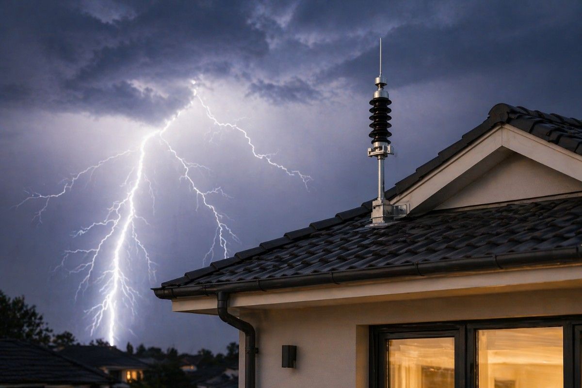
Imagine a 33kV distribution substation in rural Rajasthan during the pre-monsoon season. A dry lightning strike hits the overhead transmission line about 2 kilometers away. The resulting voltage surge travels down the line at near-light speed.
As the surge reaches the substation, the voltage at the line terminal of the horn gap lightning arrester rises sharply. At the precise sparkover voltage, the air in the series gap ionizes and the arc forms between the lower and upper horn electrodes.
The arc immediately begins rising up the diverging horns, driven by electromagnetic forces and thermal convection. Within milliseconds, the arc stretches to a length where it can no longer sustain itself. It extinguishes. The surge energy is diverted through the earth connection into the ground.
The entire event lasts less than half a second. The substation transformer, the connected feeders, and the downstream distribution network are all protected. All because 7 well-designed parts did exactly what they were supposed to do.
Common Mistakes Engineers Make with Horn Gap Lightning Arresters
Wrong Gap Setting for the Voltage Level: Using a gap setting designed for 11kV on a 33kV system is a critical error. Always match the sparkover voltage of the arrester to the system voltage and insulation level.
Ignoring Electrode Erosion: After repeated arc events, the horn electrodes erode and the gap widens. A wider gap means higher sparkover voltage, which means the arrester will not operate at the intended protection level. Inspect electrodes annually.
Skipping Insulator Cleaning: Dirty or cracked insulators cause surface leakage currents that can trigger false sparkover or prevent proper arc extinction. Clean insulators at every maintenance cycle.
Poor Earth Connection: A high-resistance earth defeats the entire purpose of the arrester. Always test earth resistance before and after installation.
Using Substandard Hardware: Cheap, uncertified mounting hardware corrodes quickly in Indian outdoor conditions, shifts electrode positions, and compromises the entire arrester assembly.
Why SPKN India Is the Right Partner for Horn Gap Lightning Arrester Requirements
Understanding the 7 parts of a horn gap lightning arrester is only half the job. The other half is sourcing a product where every one of those parts is manufactured to the right standard.
SPKN India brings decades of experience in manufacturing and supplying industrial electrical equipment across India. Here is what sets SPKN India apart when it comes to horn gap lightning arresters:
Precision Gap Setting: Every SPKN India horn gap arrester is factory-set and tested for correct sparkover voltage, eliminating the guesswork that leads to field failures.
High-Grade Electrode Material: Copper and copper alloy electrodes with superior arc erosion resistance ensure longer service life even in high-lightning-density zones.
Certified Insulator Selection: Support insulators are selected based on pollution level and creepage distance requirements, fully compliant with IEC 60815 and IS standards.
Robust Mounting Frames: Hot-dip galvanized frames fabricated to withstand Indian outdoor conditions, including coastal humidity, industrial pollution, and high wind loads.
Compliance with Standards: All products are manufactured and tested in line with IS and IEC standards applicable to surge arresters and gap-type protective devices.
Pan-India Supply and Support: From small rural distribution projects to large EPC substation contracts, SPKN India supports procurement managers, electrical contractors, and power utilities across the country with reliable products and technical guidance.
When you choose SPKN India, you are not just buying a lightning arrester. You are buying the assurance that every one of those 7 parts has been engineered to perform when it matters most.
Conclusion: Know the Parts, Make the Right Choice
A horn gap lightning arrester may look like a simple device, but each of its 7 parts plays a precise and critical role in protecting your power system. From the gap-setting that determines sparkover voltage to the earth terminal that carries surge energy safely to ground, every component matters.
For electrical engineers, procurement managers, and EPC contractors working in India's power sector, understanding these components is not just academic knowledge. It directly impacts the reliability of the systems you design, procure, and maintain.
If you are sourcing horn gap lightning arresters for a distribution substation, transmission line project, or industrial installation, partner with SPKN India for products that are built right, tested right, and backed by genuine technical expertise.
Reach out to SPKN India today for product specifications, technical datasheets, and project-specific recommendations.