Something Most People Walk Past Without Ever Noticing
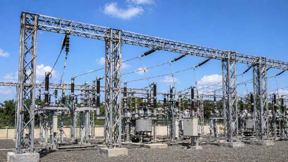
Drive past any large electrical substation in India and you will see it immediately, even if you do not know what it is. Tall steel frames rising above the compound wall, strung with conductors and insulators, holding up overhead lines that feed into transformers below.
That steel framework is the substation gantry structure. And while it does not generate power, switch circuits, or measure voltage, it makes all of those things possible.
Remove the substation gantry structure from any outdoor switchyard and the entire facility collapses into a pile of unconnected equipment. Transformers with nowhere to receive power. Isolators with nothing to mount on. Overhead lines with no termination point.
Yet in most project discussions, the gantry structure gets far less attention than the transformer it supports. Engineers debate transformer ratings for hours but finalize gantry structural drawings in minutes.
That needs to change. Because a poorly designed or incorrectly fabricated substation gantry structure does not just create a maintenance headache. It creates a safety risk that can bring down an entire substation.
This blog explains exactly what a substation gantry structure is, why it matters more than most people think, and what you need to know to specify, procure, and maintain one correctly.
Defining the Substation Gantry Structure: More Than Just a Steel Frame
A substation gantry structure is a structural steel framework erected inside an electrical substation switchyard to support overhead conductors, insulators, equipment buses, and sometimes the substation equipment itself.
The word gantry comes from engineering terminology for a bridge-like overhead frame used to support or carry loads. In a substation context, the gantry structure serves as the physical infrastructure that bridges the gap between incoming overhead transmission lines and the substation equipment at ground level.
In a typical Indian outdoor substation, the substation gantry structure performs several simultaneous functions:
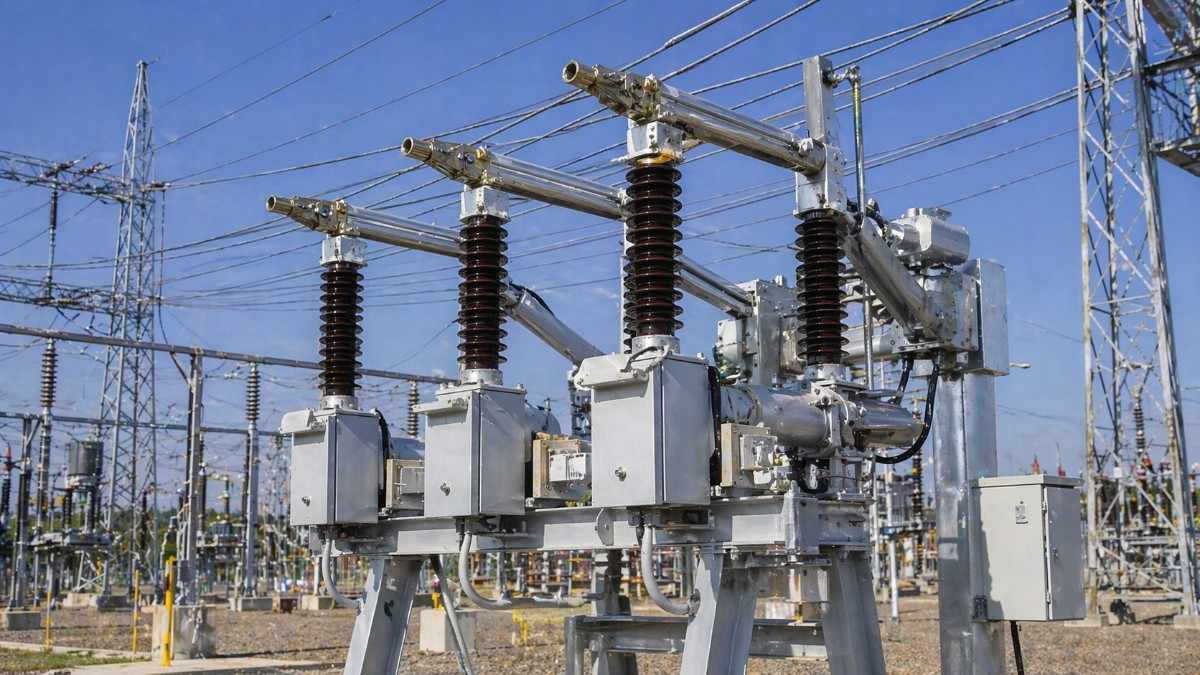
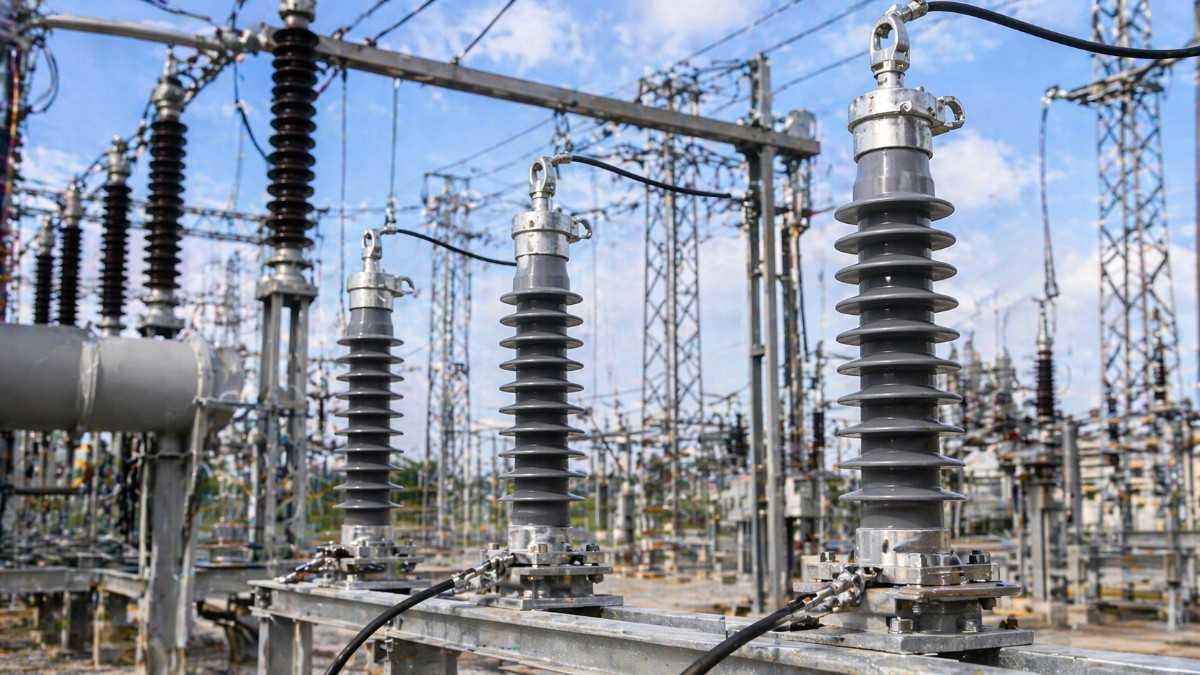
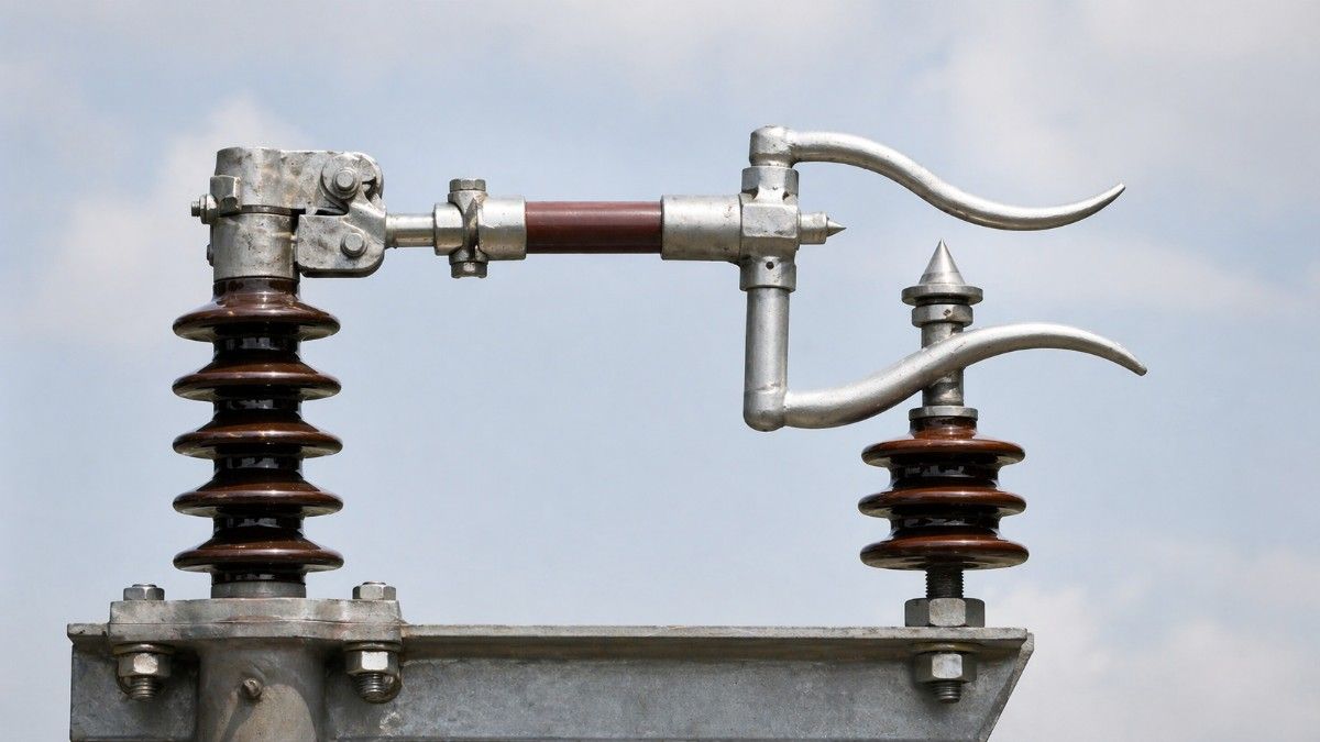
It terminates incoming overhead transmission lines and holds them at the correct height and clearance above ground. It supports strain insulators that bear the mechanical tension of overhead conductors. It provides mounting points for line isolators, earth switches, and post insulators. It forms the bus structure that connects multiple bays within the switchyard. It maintains the precise conductor-to-conductor and conductor-to-earth clearances mandated by safety standards for each voltage level.
None of these functions are glamorous. All of them are absolutely critical.
The Anatomy of a Substation Gantry Structure
Understanding what goes into a substation gantry structure helps engineers and procurement managers ask better questions and make better specifications.
Main Columns
The vertical members that carry the entire load of the structure down to the foundation. In Indian substations, main columns are typically fabricated from:
- Rolled steel sections (I-sections, H-sections, or channels) for lower voltage substations up to 33kV
- Lattice steel towers fabricated from equal or unequal angle sections for higher voltage substations at 132kV, 220kV, and 400kV
- Tubular steel sections for certain compact or aesthetic installations
The column height is determined by the minimum ground clearance required for the voltage level. For a 220kV substation, the minimum ground clearance under live conductors is 5.5 meters as per Indian Electricity Rules. The column must be tall enough to satisfy this clearance with appropriate safety margin.
Cross Arms and Horizontal Beams
These are the horizontal members that span between columns and carry the insulator strings, conductor clamps, and equipment mounting brackets. The span between columns, the conductor spacing, and the equipment weights determine the size and section of the cross arms.
For a double circuit gantry at a 132kV substation, the cross arm must simultaneously support two sets of three-phase conductors with precise phase-to-phase and phase-to-earth clearances, while resisting wind load, ice load in some northern Indian locations, and the unbalanced tension forces from the conductor spans on either side.
Foundation Stub Angles and Base Plates
The interface between the steel structure and the civil foundation. These are the most critical connections in the entire assembly because they transfer all structural loads, including wind, conductor tension, and seismic forces, into the concrete foundation below.
Incorrect foundation stub setting is one of the most common and most costly errors in substation construction in India. Once the concrete is poured and cured, a misaligned stub angle means the entire column above it is wrong, and correction is extremely expensive.
Bracing Members
Diagonal and horizontal bracing members that give the gantry structure its rigidity against lateral forces, particularly wind loads. In cyclone-prone coastal states like Andhra Pradesh, Odisha, Tamil Nadu, and West Bengal, the bracing design is absolutely critical. The substation gantry structure must withstand wind speeds as specified by IS 875 (Part 3) for the relevant wind zone.
Hardware and Clamps
Bolts, nuts, washers, U-bolts, conductor clamps, earth clamps, and all the connecting hardware that holds the structure together and attaches conductors and insulators to it. These are the smallest components and often the most neglected in procurement. Substandard hardware corrodes, loosens, and fails, creating safety hazards and maintenance nightmares.
Why the Substation Gantry Structure Matters: Six Reasons That Go Beyond the Obvious
Reason 1: It Determines Electrical Clearances and Safety
Every voltage level has mandatory minimum clearances between live conductors, between conductors and earthed metal, and between conductors and the ground. These clearances are not suggestions. They are safety requirements specified in the Indian Electricity Rules and IS standards.
The substation gantry structure is the physical mechanism that enforces these clearances. If the structure is designed incorrectly, fabricated with dimensional errors, or erected out of plumb, the clearances are compromised. A compromised clearance in a 220kV switchyard is not a minor defect. It is a potential flashover waiting for the right weather condition, the right humidity level, or the right contamination event to trigger it.
Reason 2: It Bears the Mechanical Loads of Overhead Conductors
Overhead conductors are heavy. A typical ACSR conductor used in Indian transmission networks weighs several kilograms per meter. A span of 50 to 100 meters of conductor under tension exerts significant horizontal and vertical forces on the termination point at the gantry.
Add to this the wind pressure on the conductors themselves, the dynamic loads during short circuit events when conductors swing violently due to electromagnetic forces, and the thermal expansion forces as conductor temperature varies between a cold winter night in Punjab and a hot summer afternoon in Rajasthan, and you have a complex mechanical loading scenario that the substation gantry structure must handle continuously for 30 to 40 years.
Reason 3: It Must Survive Indian Weather Extremes
India is not a single climate. A substation gantry structure in Leh, Ladakh experiences temperatures below minus 20 degrees Celsius and potential ice loading on conductors. A structure in coastal Chennai faces salt-laden humidity and cyclonic wind speeds. One in the industrial belt of Ankleshwar, Gujarat faces chemical pollution that aggressively attacks steel surfaces.
The material selection, surface treatment, and coating system for a substation gantry structure must be matched to the specific environmental conditions of the installation site. A one-size-fits-all approach to substation gantry structure procurement leads to premature corrosion, structural degradation, and shortened service life.
Reason 4: It Directly Impacts Substation Expandability
Substations are not built once and forgotten. Load growth, new industrial connections, and grid expansion requirements mean that most substations need to be expanded at some point in their operating life. Adding a new feeder bay, a new transformer, or a new busbar section all require modifications or extensions to the substation gantry structure.
A well-designed gantry structure with adequate bay spacing, modular column design, and documented as-built drawings makes future expansion straightforward. A poorly designed or poorly documented structure makes every expansion project a structural engineering investigation exercise.
Reason 5: It Affects Construction Schedule and Project Cost
The substation gantry structure is typically one of the first items erected on a substation site after civil foundations are complete. Every other major activity, conductor stringing, insulator hanging, equipment installation, depends on the gantry structure being in place and correctly aligned.
Fabrication errors, dimensional mistakes, or late delivery of the gantry structure creates a cascade of delays across the entire project schedule. In EPC substation projects in India where liquidated damages apply for delayed commissioning, a gantry structure problem is a project management crisis.
Reason 6: It Is a Long-Term Safety Asset Requiring Proper Maintenance
A substation gantry structure that is properly designed and maintained will last 40 years or more. One that is neglected will begin developing problems within a decade, and those problems compound over time.
Corrosion at base plates, loose foundation bolts, cracked welds, degraded galvanizing, and damaged bracing connections all weaken the structure progressively. In a worst-case scenario, a structurally compromised gantry collapses under wind load, bringing down live conductors and causing a major substation outage combined with serious safety hazards.
Types of Substation Gantry Structure Used in Indian Substations
Indian substation projects use several configurations of gantry structure depending on the voltage level, the substation layout, and the specific application within the switchyard.
Single Circuit Gantry
Supports one set of three-phase conductors. Used at line entry points where a single transmission line terminates into the substation. Common at 33kV and 66kV substations with limited line circuits.
Double Circuit Gantry
Supports two sets of three-phase conductors simultaneously, one above the other or side by side. Used where two transmission lines terminate at the same gantry location. Requires careful phase arrangement to maintain clearances between the two circuits.
Bus Support Structure
Supports the main busbar conductors within the switchyard. May be a portal frame, an A-frame, or a lattice structure depending on the conductor configuration and the span required. Bus support structures must also accommodate post insulators, strain insulators, and the mounting hardware for bus isolators.
Equipment Support Structure
Some substation equipment, particularly current transformers, voltage transformers, and line isolators at higher voltage levels, is mounted on dedicated steel support structures within the gantry framework. These structures must be precisely dimensioned to position equipment at the correct height and alignment for connection to the conductor system.
Shielding Mast Structure
Tall masts erected at corners and along the perimeter of the switchyard to support lightning protection shielding wires that protect the open-air equipment below from direct lightning strikes. The shielding mast is a specialized form of substation gantry structure with specific height and positioning requirements determined by the shielding angle calculations for the switchyard.
Design Standards Every Engineer Must Know
Any substation gantry structure used in Indian power projects must be designed and fabricated in compliance with relevant Indian and international standards. Key standards include:
IS 800: Code of practice for general construction in steel. The fundamental standard governing the structural design of steel members used in substation gantry structures.
IS 802: Code of practice for use of structural steel in overhead transmission line towers. Applicable for lattice-type gantry structures used at higher voltage levels.
IS 875 (Part 3): Code of practice for design loads for buildings and structures, specifically wind loads. The wind load calculation for any substation gantry structure in India must be based on the basic wind speed for the specific location as given in IS 875.
IS 2062: Standard for hot rolled medium and high tensile structural steel. Specifies the material grade for structural steel sections used in fabrication. Grade E250 and E350 are most commonly used in Indian substation gantry structures.
IS 4759: Hot dip zinc coatings on structural steel. Governs the galvanizing specification for corrosion protection.
CEA (Technical Standards for Construction of Electrical Plants and Electric Lines) Regulations: The Central Electricity Authority regulations that specify clearance requirements and structural safety requirements for substations at various voltage levels.
Fabrication and Erection: Where Projects Go Wrong
Even a perfectly designed substation gantry structure can become a problem if fabrication and erection are not executed correctly. Here are the most common failure points in Indian substation construction practice:
Dimensional Errors in Fabrication: Holes drilled at wrong locations, members cut short, and column lengths fabricated incorrectly. These errors are discovered during erection, at which point correction is expensive and time-consuming.
Poor Weld Quality: Incomplete fusion welds, undercut welds, and welds on the wrong side of members. Weld defects in primary structural members reduce the load-carrying capacity and create stress concentration points for fatigue cracking.
Inadequate Galvanizing: Thin or patchy galvanizing that fails within a few years in aggressive environments. Always verify galvanizing thickness against IS 4759 requirements using a calibrated thickness gauge before accepting material on site.
Foundation Stub Misalignment: As mentioned earlier, this is one of the costliest errors. Foundation stub angles must be set using precision surveying instruments and carefully checked before concrete is poured.
Incorrect Erection Sequence: Erecting gantry columns and cross arms without following the designed erection sequence can lead to overloading of partially erected members and potential structural instability during construction.
Skipping Pre-Erection Trial Assembly: For complex gantry structures, a trial assembly at the fabrication shop before dispatch to site catches dimensional errors before they become site problems.
Maintenance: The Discipline That Extends Service Life by Decades
A proactive maintenance programme for substation gantry structures is the difference between a structure that serves reliably for 40 years and one that becomes a safety liability in 15 years.
A good maintenance schedule should include:
Annual Visual Inspection: Check for corrosion at base plates and below-ground interfaces, loose bolts and connections, damaged galvanizing or paint, cracks in welds, and physical damage from vehicle impact or wildlife.
Bolt Torque Verification: Foundation bolts and primary connection bolts should be checked for correct torque at least every three years. Thermal cycling and vibration cause bolts to loosen over time.
Galvanizing Touch-Up: Areas where galvanizing has been damaged by installation activities or mechanical impact should be treated with zinc-rich paint as a touch-up measure to prevent corrosion propagation.
Structural Inspection After Extreme Weather Events: After a cyclone, a seismic event, or an unusually severe storm, a detailed structural inspection should be conducted before the substation is returned to full service.
Conductor and Insulator Hardware Check: The clamps, U-bolts, and suspension hardware connecting conductors to the gantry structure should be inspected for wear, corrosion, and correct tension.
Why SPKN India Is the Right Partner for Substation Gantry Structure Requirements
Across India, substation project teams face a consistent challenge: finding a supplier who understands not just how to fabricate steel, but how substation gantry structures actually function, what loads they carry, what standards they must meet, and what the consequences of getting it wrong are.
SPKN India brings that understanding to every project.
Engineering-Led Design: SPKN India approaches every substation gantry structure requirement with a proper engineering analysis, not just a standard template. Wind zone, soil conditions, voltage level clearances, conductor loading, and future expansion requirements are all factored into the design.
IS and CEA Standards Compliance: Every substation gantry structure fabricated by SPKN India is designed and produced in compliance with IS 800, IS 802, IS 2062, IS 875, and CEA regulations, giving project engineers and owners the assurance of a code-compliant structural solution.
Quality Steel and Hot-Dip Galvanizing: SPKN India uses IS 2062 Grade E250 and E350 structural steel with hot-dip galvanizing to IS 4759 standards, ensuring corrosion protection that matches the service life requirements of substation infrastructure.
Precise Fabrication: CNC-controlled drilling and cutting operations ensure dimensional accuracy that eliminates the site-level fitting problems that plague poorly fabricated structures.
Complete Documentation: SPKN India provides fabrication drawings, material test certificates, galvanizing inspection reports, and as-built documentation as standard deliverables, supporting project quality records and future maintenance programmes.
Pan-India Project Experience: From 11kV distribution substations in rural Madhya Pradesh to 400kV grid substations in Rajasthan and Maharashtra, SPKN India has supplied substation gantry structures across voltage levels and geographies, bringing genuine field experience to every new project.
EPC Partner Support: For EPC contractors working on tight schedules, SPKN India offers fabrication-to-delivery timelines that fit project programmes, with proactive communication on fabrication progress and dispatch schedules.
When you specify a substation gantry structure for your next project, the choice of fabricator is as important as the design itself. SPKN India gives you both.
Conclusion: The Substation Gantry Structure Is the Foundation of Everything Above It
The substation gantry structure does not make the headlines when it works. It only makes the headlines when it fails. And by then, the consequences are already severe.
For electrical engineers designing switchyards, procurement managers sourcing structural components, and EPC contractors building substations across India, understanding what a substation gantry structure is and why it matters is the first step toward getting it right.
It is not just a steel frame. It is the physical infrastructure that makes every other piece of substation equipment work safely, reliably, and at the correct electrical clearances for decades.
Specify it correctly. Procure it from a manufacturer who understands both the structural and electrical requirements. Maintain it proactively. And partner with SPKN India for a substation gantry structure that is engineered to perform for the full lifecycle of your substation.
Contact SPKN India today for project-specific design consultation, fabrication drawings, material specifications, and delivery timelines for your next substation project.