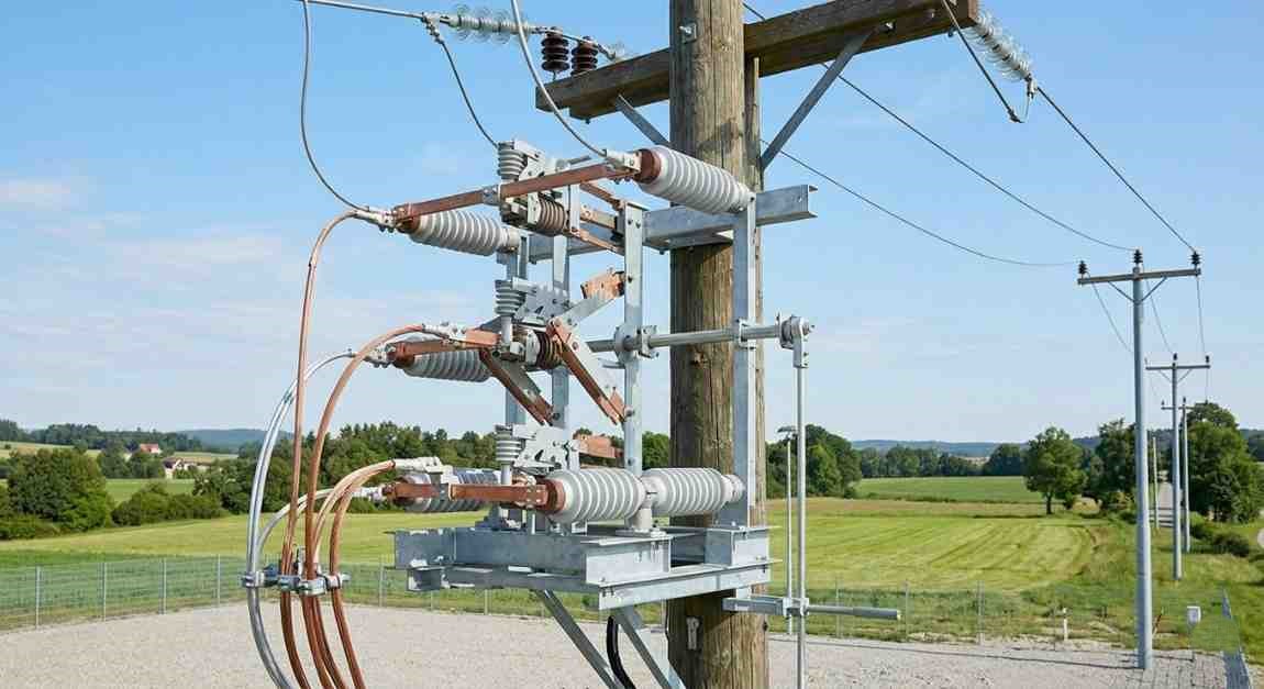
Whether you are specifying equipment for a new substation, replacing an ageing isolator on an overhead line, or simply trying to understand what that large outdoor switch assembly actually does, this guide covers everything with clarity and no shortcuts.
What Is a 33kV Air Break Switch?
A 33kV air break switch is a manually or motorised-operated switching device used in medium voltage overhead distribution and transmission networks to isolate sections of a 33kV line or substation under no-load or minimal load conditions.
The name gives away the operating principle. When the switch opens, the electrical circuit is broken in open air. The arc that forms as the contacts separate is extinguished naturally by the surrounding atmosphere, aided by the physical distance the contacts travel during opening.
It is important to understand from the start what this switch is and what it is not. A 33kV air break switch is not a circuit breaker. It is not designed to interrupt fault currents or heavy load currents. Its job is isolation and sectionalising, performed safely under controlled conditions where current flow is minimal or absent.
In my experience, one of the most common mistakes made on distribution projects is specifying an air break switch where a load break switch or circuit breaker is actually needed. Getting that distinction right from the specification stage saves enormous rework costs later.
How Does a 33kV Air Break Switch Work?
The operating mechanism is straightforward but the engineering behind reliable performance at 33kV is more involved than it appears.
When the switch is operated, the moving contact arm rotates away from the fixed contact, creating a gap through which the circuit is broken. At 33kV, the electric field across that gap is substantial. The contacts must travel far enough apart to prevent the arc from being sustained and to provide a visible, verifiable isolation gap that satisfies safety requirements.
Air serves as the insulating medium between open contacts. This is why the design, geometry, and spacing of the contacts must be precise. Contamination on insulators, incorrect contact pressure, or worn contact surfaces can all compromise the reliability of the break.
Most 33kV air break switches use a rotating blade or knife-blade mechanism. The blade pivots on a central insulator and swings away from the fixed jaw contact at each end. This gives operators and safety inspectors a clearly visible open position, which is one of the key safety requirements for isolation devices in any high voltage installation.
Types of 33kV Air Break Switches
Not every 33kV air break switch is the same. The right type depends on your application, mounting arrangement, and operational requirements.
Single Pole Air Break Switch
Each phase is switched independently. These are common on overhead distribution lines where individual phase isolation is required. They can be operated manually using a hotstick or through a gang operating mechanism.
Gang Operated Air Break Switch
All three phases are mechanically linked and operated simultaneously through a single handle or motorised actuator. Gang operation is essential where simultaneous three-phase isolation is required, which covers the vast majority of substation and feeder switching applications.
Double Break Air Break Switch
The contact arm breaks at two points simultaneously, one at each end of the rotating blade. This doubles the arc gap and improves the switch's ability to interrupt small capacitive or magnetising currents that may be present even under nominally no-load conditions.
Single Break Air Break Switch
The circuit is broken at one point only. Simpler and more compact, these are suited to applications where the switching duty is straightforward and load current interruption is not required.
Motorised Air Break Switch
Fitted with an electric motor and remote control interface. Used where manual operation is impractical due to location, height, or the need for SCADA integration in automated distribution networks. Increasingly common in modern smart grid deployments.
Vertical Break vs. Horizontal Break
Vertical break switches open the blade upward, which is the more traditional design and easier to visually verify from ground level. Horizontal break switches rotate the blade in a horizontal plane, which suits certain mounting configurations and compact substation layouts.
Key Components of a 33kV Air Break Switch
Understanding what makes up the switch helps you evaluate quality and specify correctly.
- Moving Contact (Blade): The rotating arm that carries current when closed and creates the isolation gap when open
- Fixed Contacts (Jaw Contacts): The receiving terminals at each end that grip the blade firmly when closed
- Insulators: Post insulators or pin insulators that support live components and isolate them from the earthed structure
- Operating Mechanism: The linkage, shaft, and handle or motor drive that transmits operating force to the blade
- Gang Operating Rod: The mechanical link that synchronises all three phases in gang-operated configurations
- Earthing Blades (Optional): Some switches are fitted with integral earth blades that ground the isolated circuit after opening, providing additional safety for maintenance personnel
- Mounting Structure: Hot-dip galvanised steel framework that supports the entire assembly on poles or substation gantries
- Arc Horns: Fitted on some designs to guide and extinguish the arc during opening, particularly where small inductive or capacitive currents may be present
Where Is a 33kV Air Break Switch Used?
The applications are widespread across the power distribution and transmission sectors.
Overhead Line Sectionalising: Installed at strategic points along 33kV overhead feeders to allow sections of the line to be isolated for maintenance or fault repair without de-energising the entire feeder.
Distribution Substations: Used as incoming or outgoing isolators at 33kV distribution substations, providing visible isolation before maintenance on transformers, cables, or switchgear.
Transformer Isolation: Installed on the 33kV primary side of distribution transformers to allow the transformer to be safely isolated and earthed for maintenance.
Ring Main Switching Points: In 33kV ring or looped distribution networks, air break switches are installed at switching points to allow network reconfiguration under no-load conditions.
Tee-Off Points on Feeders: Where branch feeders tap off from a main 33kV line, an air break switch provides the ability to disconnect the branch independently.
Industrial and Utility Substations: Large industrial consumers taking supply at 33kV typically have incoming air break switches or disconnectors as part of their metering and protection arrangements.
When I tried commissioning a 33kV ring main switching arrangement for an industrial estate in Haryana, the gang-operated motorised air break switches at the feeder junction points were the only practical solution. Manual operation at those locations was neither safe nor operationally realistic given the access constraints.
33kV Air Break Switch vs. Load Break Switch vs. Circuit Breaker
This comparison comes up on almost every project, and it is worth being very clear about the differences.
33kV Air Break Switch: Designed for no-load switching only. Opens and closes under conditions where current is negligible. Provides visible isolation. Not suitable for interrupting load current or fault current.
33kV Load Break Switch: Specifically designed to open and close under full load current. Uses arc quenching technology (SF6 gas, vacuum, or oil) to safely interrupt load current. Still not suitable for fault current interruption.
33kV Circuit Breaker: Designed to interrupt both load current and fault current rapidly and reliably. Used as the primary protection device. Does not necessarily provide visible isolation in the same way an open-blade switch does.
In a properly designed 33kV installation, you will typically find all three working together. The circuit breaker provides fault protection. The load break switch allows operational switching. The air break switch provides the visible, lockable isolation point that makes it safe to work on the downstream equipment.
I have noticed that cost-cutting exercises on smaller projects sometimes attempt to eliminate one of these layers. That almost always creates either a safety gap or an operational inconvenience that proves more expensive to remedy later.
Standards and Specifications for 33kV Air Break Switches
Any 33kV air break switch used in India should comply with relevant national and international standards. This is not a box-ticking exercise. Standards exist because the failure modes of high voltage equipment are well understood and the consequences of failure are serious.
Key standards applicable to 33kV air break switches include:
- IS 9921: Indian standard for alternating current disconnectors and earthing switches
- IEC 62271-102: International standard covering AC disconnectors and earthing switches for voltages above 1 kV
- IS 2544: Standard for porcelain post insulators used in electrical apparatus
When specifying, the following parameters must be confirmed:
- Rated Voltage: Must be 36 kV (the standard rated voltage for equipment used on 33kV systems, providing margin above the nominal)
- Rated Normal Current: The continuous current the switch can carry without exceeding temperature limits
- Short Time Withstand Current (Ith): The fault current the closed switch can withstand for a specified duration without damage
- Peak Withstand Current (Ip): The maximum instantaneous fault current the switch can withstand
- Power Frequency Withstand Voltage: The AC voltage the insulation must withstand without breakdown
- Lightning Impulse Withstand Voltage (BIL): Resistance to transient overvoltages from lightning
- Degree of Protection (IP Rating): For any enclosed operating mechanism boxes
Installation and Maintenance Considerations
A well-specified air break switch that is poorly installed or neglected will fail at the worst possible moment. Here is what good installation and maintenance practice looks like.
During Installation:
The mounting structure must be level, properly aligned, and adequately braced. Misalignment puts mechanical stress on insulators and operating linkages that leads to premature failure. Contact pressure must be set correctly. Too little pressure causes overheating. Too much causes mechanical damage during operation.
Phase-to-phase and phase-to-earth clearances must be verified after installation and must meet the minimum values specified for 33kV equipment.
Routine Maintenance:
Regular inspections should cover contact condition and cleanliness, insulator condition (looking for cracks, chips, tracking marks, or contamination), operating mechanism lubrication, tightness of all bolted connections, and correct operation through a full open-close cycle.
In my experience, the contacts and the insulator surfaces are where problems develop first. Pitting or burning on contacts indicates the switch has been operated under current conditions it was not designed for. Tracking marks on insulators indicate pollution or moisture ingress that will eventually lead to flashover if not addressed.
Earthing:
The mounting structure must be properly earthed. If the switch is fitted with integral earth blades, the earthing connections must be verified and the earth blade operating sequence must be clearly understood by all operators.
Choosing the Right 33kV Air Break Switch for Your Project
There is no universal answer because every application has its own specific requirements. But here is a practical checklist to guide the selection process.
- Confirm the rated voltage class (36 kV for 33kV systems)
- Determine the required continuous current rating based on maximum load
- Check the short time withstand current against your system's fault level
- Decide on single pole or gang operation based on your switching philosophy
- Specify motorised or manual operation based on location and operational requirements
- Confirm whether integral earth blades are required by your safety rules
- Verify that the switch meets IS 9921 or IEC 62271-102
- Check that the supplier can provide type test certificates from an accredited laboratory
SPKN India supplies 33kV air break switches and associated switching equipment across India, supporting projects in industrial, utility, and infrastructure sectors. With clients in Hyderabad, Mumbai, Delhi, Bengaluru, Chennai, and beyond, SPKN India understands the technical and compliance requirements that come with operating at 33kV.