There is a substation in a chemical processing zone in Gujarat that went through three earthing system failures in five years. Each time, the earth resistance crept up beyond acceptable limits during summer, equipment protection systems started behaving erratically, and maintenance teams had to scramble for emergency remediation.
The root cause was not a bad product. It was a bad installation matched to the wrong soil conditions.
Earthing Electrode Installation in India is one of those topics that gets underestimated until something goes wrong. Engineers specify the electrode type, the contractor drives it into the ground, and everyone moves on. What they miss is that soil resistivity varies dramatically across Indian geographies, seasonal moisture changes affect resistance values significantly, and installation depth and backfill treatment determine whether the system will still perform reliably a decade later.
This blog lays out what genuinely works in Indian field conditions, what commonly fails, and how to approach earthing electrode selection and installation the right way.
Why Earthing Systems Fail More Often Than They Should
The purpose of an earthing electrode is straightforward. It provides a low-resistance path between an electrical system and the general mass of earth, enabling fault current to flow safely, equipment protection to operate correctly, and personnel to be protected from dangerous touch and step voltages.
When that path degrades, everything downstream suffers.
In India, earthing system failures typically trace back to four root causes:
- Electrode material that corrodes faster than the design assumed
- Insufficient installation depth for the local water table and soil moisture profile
- No backfill treatment in high-resistivity soils like rocky terrain, sandy ground, or laterite zones
- No periodic testing or maintenance after commissioning
The Indian electrical industry has been gradually improving on all four fronts, but inconsistent installation practices across EPC contractors remain a persistent problem.
The Soil Challenge Across Indian Geographies
Before discussing electrode types and installation methods, this point needs to be understood clearly: India does not have uniform soil conditions.
A coastal site in Kerala has moist, conductive soil with naturally low resistivity. An installation there might achieve target earth resistance values with a single copper-bonded rod at 3 meters depth.
A rocky site in Rajasthan or a laterite plateau in Karnataka might show soil resistivity of 3000 ohm-meters or higher. The same rod at the same depth achieves almost nothing. Without chemical backfill treatment and a carefully engineered electrode arrangement, the system will never meet IS 3043 requirements.
This geographical variability is why soil resistivity testing using the Wenner four-pin method is not optional. It is the foundation of every credible earthing system design. Any EPC contractor or installation team skipping this step is guessing, and guessing with earthing systems has real consequences.
Types of Earthing Electrodes Used in Indian Installations
Understanding the options helps engineers and procurement managers match the electrode type to the application and soil conditions.
Copper Bonded Steel Rods
This is the most widely used electrode type in modern Indian industrial and utility installations. A high-tensile steel core is electrolytically bonded with a copper layer of typically 250 microns thickness. The steel provides mechanical strength for driving into dense soil, while the copper layer delivers the corrosion resistance and electrical conductivity needed for long-term performance.
Copper bonded rods conform to IS 3043 and are available in standard diameters of 14.2 mm and 17.2 mm, with lengths from 1.5 meters to 3 meters per section. Couplers allow multiple sections to be joined for deeper installations.
Pure Copper Rods and Plates
Used in critical installations where corrosion resistance is paramount and the budget supports it. Pure copper electrodes have excellent conductivity and long service life but are significantly more expensive and prone to theft at unmanned installation sites, which is a real operational consideration across rural and semi-urban Indian locations.
Galvanized Iron Rods and Plates
An older technology that still appears in lower-specification industrial projects and older residential installations. GI electrodes corrode relatively quickly in acidic or high-chloride soils, which are common near coastal areas and chemical plants. Their use in new critical installations is not recommended.
Chemical Earthing Electrodes
These are prefabricated electrodes containing hygroscopic compounds (typically bentonite, graphite, and conductive salts) that are activated by water. They are designed specifically for high-resistivity soils where conventional rod electrodes cannot achieve acceptable resistance values. Chemical earthing electrodes absorb moisture from the environment, maintain soil moisture around the electrode, and significantly lower the contact resistance with surrounding soil.
They are the preferred solution for rocky terrain, desert environments, and sites with seasonal soil drying.
Maintenance-Free Earthing Electrodes
An advanced variant of the chemical earthing electrode, designed with a sealed outer casing that prevents the conductive compound from depleting over the design life. These are specified in critical infrastructure projects, data centres, telecommunications towers, and renewable energy plants where long-term reliability without maintenance intervention is essential.
A Comparison: Conventional Rod Electrode vs Chemical Earthing Electrode
This is a question that comes up regularly in project specifications.
| Parameter | Copper Bonded Rod | Chemical Earthing Electrode |
|---|---|---|
| Best suited soil | Low to medium resistivity | High resistivity, rocky, sandy |
| Installation depth required | Typically 3 to 6 meters | 2 to 3 meters standard |
| Backfill treatment needed | Yes, in high-resistivity soil | Self-contained hygroscopic backfill |
| Seasonal resistance variation | High in dry seasons | Low, compound retains moisture |
| Maintenance requirement | Periodic testing and backfill top-up | Minimal for maintenance-free type |
| Cost consideration | Lower initial cost | Higher initial, lower lifecycle cost |
| Application examples | Industrial plants, substations in normal soil | Telecom towers, solar plants, rocky sites |
The right choice depends on your soil, your application criticality, and your long-term maintenance capability. Both types have their place in Indian earthing practice.
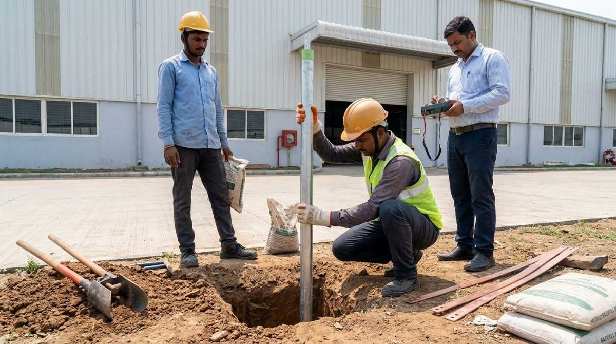
Step-by-Step: What a Correct Earthing Electrode Installation Looks Like
This is where installation quality either makes or breaks the system performance.
Soil Resistivity Testing First
Conduct the Wenner four-pin method test at multiple depths across the installation site. Plot the resistivity profile and use it to determine electrode depth, spacing, and backfill requirements. This data feeds into the earth system design and determines how many electrodes are needed to achieve the target resistance value.
Excavation and Pit Preparation
For chemical earthing electrodes, excavate a pit of the dimensions specified by the manufacturer, typically 150 mm diameter and 2 to 3 meters deep. For copper bonded rod installations, the rod is driven directly using a driving hammer or pneumatic driver. Do not use excessive impact force that deforms the coupling threads between rod sections.
Backfill Treatment
In standard soil conditions with copper bonded rods, surround the electrode with a bentonite-charcoal mixture in a 3:1 ratio extending at least 150 mm around the electrode on all sides. This backfill retains moisture, improves soil-to-electrode contact, and reduces seasonal resistance variation.
For chemical earthing electrodes, follow the manufacturer's activation procedure, which typically involves watering the installed electrode to activate the hygroscopic compound before backfilling the pit.
Electrode Connection
Connect the earthing conductor to the electrode using an exothermic welding process (Cadweld or equivalent) rather than bolted clamps wherever possible. Exothermic welds create a molecular bond that has lower resistance and better corrosion resistance than mechanical connections. Mechanical clamps corrode at the interface over time, increasing the connection resistance even when the electrode itself is still in good condition.
Bolted connections, when used, must be made with tinned copper lugs, stainless steel bolts, and anti-corrosion compound application. Inspect and re-torque at every maintenance cycle.
Earth Resistance Testing After Installation
Measure the earth resistance using the fall-of-potential method (three-point method) per IS 3043. The acceptable resistance value depends on the application.
| Application | Maximum Earth Resistance (IS 3043) |
|---|---|
| HV and EHV substations | 1 ohm or less |
| LV distribution transformers | 2 ohm |
| Industrial plant equipment | 5 ohm |
| Telecommunications and IT | 1 ohm or less |
| Lightning protection systems | Less than 10 ohm |
If the measured value exceeds the target, additional electrodes must be added and connected in parallel before the installation is accepted.
Real-World Scenario: Solar Power Plant Earthing in High-Resistivity Terrain
A 25 MW solar plant project in the Deccan plateau region of Maharashtra faced soil resistivity readings averaging 1800 ohm-meters across the inverter station area. Standard copper bonded rod installations at 3-meter depth were achieving earth resistance values of 28 to 35 ohms, far above the 1-ohm requirement for the MV connection point.
The solution involved maintenance-free chemical earthing electrodes installed at 3-meter depth in a cluster arrangement, with interconnecting copper conductors running between electrodes. The cluster configuration reduced effective earth resistance to below 0.8 ohms. The self-contained hygroscopic compound in each electrode ensured stability through the dry summer months when the red laterite soil loses nearly all its moisture.
This is a project outcome that was only possible because the soil resistivity data was taken seriously from day one, and the electrode type was selected to match the actual site conditions rather than defaulting to a standard specification.
What SPKN India Brings to Earthing Electrode Installation Projects
SPKN India has positioned itself as more than just a product supplier in the Indian earthing equipment space. The combination of technically verified products and application-specific support is what makes the difference for engineers and EPC contractors dealing with the real complexity of Indian site conditions.
SPKN India's earthing electrode range includes copper bonded steel rods conforming to IS 3043, chemical earthing electrodes for high-resistivity applications, maintenance-free electrodes for critical infrastructure projects, and complete earthing system accessories including backfill compounds, exothermic welding kits, and earthing conductors.
Every product is manufactured under quality management systems aligned with IS and IEC standards, and type test certificates are available for technical review. For utility and industrial projects requiring documentation for electrical inspectorate approval, SPKN India provides the complete product certification package as standard.
For EPC contractors, the value goes beyond the product. SPKN India's technical team provides guidance on soil resistivity interpretation, electrode count and spacing calculations, and backfill selection based on site-specific conditions. This application engineering support prevents the most common and costly installation errors before they happen.
Procurement managers dealing with large project requirements benefit from consistent product quality across batches, reliable delivery schedules, and a manufacturer who understands both IS standards and the practical realities of Indian substation and industrial construction.
Five Mistakes That Undermine Earthing Electrode Installations in India
Even experienced contractors repeat these errors.
Using GI rods in coastal or chemical environments Galvanized iron corrodes rapidly in chloride-rich or acidic soils. Within three to five years, GI electrodes in these environments show significant material loss and rising resistance values.
Installing at insufficient depth during the dry season Shallow electrodes stay within the zone of seasonal soil drying. An installation that tests fine in February may fail resistance requirements by May in states like Rajasthan, Telangana, or Maharashtra.
Connecting the earthing conductor with an unprotected bolted clamp Bimetallic corrosion at the clamp-electrode interface is one of the most common causes of rising earth resistance in systems that tested correctly at commissioning.
Not testing after backfill settlement Earth resistance values can change after the backfill compacts and settles around the electrode. A retest at 30 days after installation gives a more reliable picture of actual performance.
Assuming one electrode is enough for high-resistivity sites A single electrode in rocky or dry soil almost never meets the target resistance for industrial or substation applications. Always design for parallel electrode clusters in high-resistivity conditions.
Conclusion
The quality of Earthing Electrode Installation in India determines the safety and reliability of every piece of electrical equipment connected to that system. It is not a background task or a civil contractor's afterthought. It is an engineering discipline that requires correct soil assessment, matched product selection, proper installation technique, and verified post-installation testing.
Whether you are commissioning a new industrial plant, building a grid substation, or retrofitting an earthing system that has been underperforming for years, the fundamentals do not change. Get the soil data. Match the electrode to the conditions. Install correctly. Test and document.
SPKN India is equipped to support every stage of that process, from product supply to technical consultation. Reach out to the SPKN India team with your site conditions and project requirements, and get an earthing system solution that will actually perform across seasons and years.