I've spent a good chunk of my career around transmission planning and grid design, and one pattern keeps showing up: the projects that build in redundancy from day one almost always perform better over their lifespan than the ones that try to save space or material upfront.
So let's break down what a double circuit transmission line actually is, why utilities increasingly prefer it, and what factors matter when planning one.
What Is a Double Circuit Transmission Line, Really
Picture a single road versus a two-lane highway. A single road works fine until there's an accident, construction, or heavy traffic, then everything backs up with no alternative route. A two-lane highway gives you flexibility. If one lane shuts down, traffic can still flow through the other.
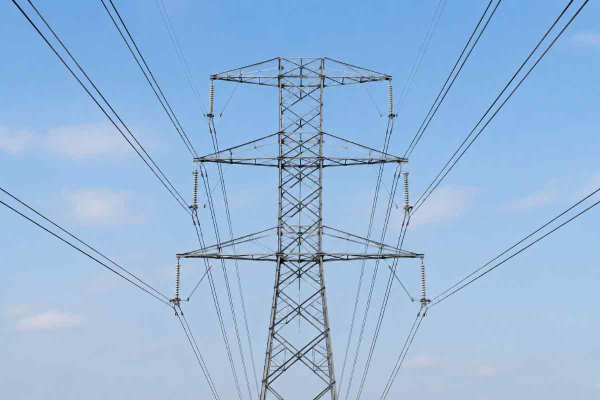
A double circuit transmission line works on the same logic. Instead of running one set of three-phase conductors on a tower, it carries two complete circuits on the same structure. If one circuit needs maintenance or experiences a fault, the other can continue carrying load.
This isn't just a nice-to-have feature. For critical infrastructure like hospitals, industrial zones, or urban centers, that redundancy can mean the difference between a brief blip and a multi-hour outage.
How It Differs From a Single Circuit Line
A single circuit transmission line carries just one three-phase circuit per tower. It's simpler, often cheaper to build initially, and works fine for lower-priority routes with limited load requirements.
In my experience, the real decision point comes down to reliability requirements and right-of-way constraints. If land acquisition is difficult or expensive, doubling up circuits on one tower line makes a lot of sense rather than building two separate lines.
Why Utilities Are Increasingly Choosing Double Circuit Designs
I've noticed that grid planners have shifted noticeably toward double circuit configurations over the past decade, and it's not just a trend. There are solid engineering reasons behind it.
Key advantages that drive this shift include:
- Improved reliability through built-in redundancy if one circuit faults
- Better land utilization, since two circuits share one right-of-way corridor
- Lower long-term costs compared to building two separate single circuit lines
- Easier maintenance scheduling, since one circuit can stay live while the other is serviced
- Higher power transfer capacity within the same physical footprint
According to data referenced by the Central Electricity Authority on transmission network planning, double circuit configurations have become the preferred standard for a significant share of new 132kV and above transmission corridors in India, largely due to land constraints and reliability mandates.
A Real Example Worth Mentioning
When I worked on reviewing a transmission corridor proposal a few years ago for a growing industrial belt, the original plan called for two separate single circuit lines running parallel routes. The land acquisition alone would have taken considerably longer and cost more in compensation.
Switching to a double circuit design on a single right-of-way solved both problems at once. It wasn't a complicated decision once the numbers were laid out, but it took someone actually running the comparison to make that clear.
Design Considerations for Double Circuit Transmission Lines
Building a double circuit line isn't just about doubling the conductors on a tower. There are specific engineering factors that need careful attention.
- Tower configuration and conductor spacing — adequate clearance between circuits prevents flashover risk
- Conductor sag and tension calculations — must account for the additional load of two circuits
- Insulation coordination — both circuits need proper insulation levels for the voltage class
- Foundation design — towers carrying double circuits experience different load distributions
- Lightning and surge protection — proper grounding and shielding wires matter even more given the higher value at stake
I've noticed that the biggest design oversights tend to happen around conductor spacing. Get this wrong, and you increase the risk of a fault on one circuit affecting the other, which defeats the entire purpose of the redundancy.
Vertical vs Horizontal Circuit Arrangement
Double circuit towers typically arrange the two circuits either vertically (stacked on top of each other) or in a more horizontal configuration depending on terrain and tower height constraints.
Vertical arrangements tend to be more common in India due to narrower right-of-way corridors in urban and semi-urban areas. Horizontal layouts show up more often where land is less constrained, such as certain rural transmission corridors.
Where Double Circuit Transmission Lines Make the Most Sense
Not every transmission project needs a double circuit configuration, and it's worth being realistic about when the extra investment pays off.
- Urban and industrial load centers where outage tolerance is low
- Areas with limited right-of-way availability where land acquisition is difficult
- Critical infrastructure corridors feeding hospitals, data centers, or essential services
- Renewable energy evacuation routes where consistent power transfer matters for grid stability
When I tried evaluating a rural feeder extension project that didn't have these pressures, a single circuit line actually made more practical sense. Redundancy is valuable, but it's not free, and matching the design to actual reliability needs matters more than defaulting to the "better" option every time.
How SPKN India Supports Transmission Infrastructure Projects
At SPKN India, we work with EPC contractors and utility planners on transmission infrastructure components that need to perform reliably across decades of service, not just pass initial commissioning tests.
We've found that double circuit transmission line projects succeed most when the planning phase accounts for long-term load growth, not just current demand. Designing for today's numbers alone often leads to costly retrofits later.
Our team at SPKN India has supported projects ranging from substation equipment to line accessories, always with an eye toward how the infrastructure will actually perform once it's energized and under real-world stress.
Common Mistakes in Double Circuit Line Planning
A few recurring issues show up across projects, and they're worth flagging directly.
Underestimating future load growth. Conductor sizing and tower design should account for reasonable load increases over the line's service life, not just immediate requirements.
Insufficient inter-circuit clearance. Cutting corners on spacing to save tower height creates fault propagation risks that undermine the entire redundancy benefit.
Inadequate grounding design. Both circuits need robust grounding, especially in lightning-prone regions, to actually deliver the reliability the design promises.
Ignoring maintenance access. Towers and conductor configurations should allow safe maintenance of one circuit while the other remains energized, otherwise the redundancy benefit gets lost in practice.
Final Thoughts on Planning a Double Circuit Transmission Line
A double circuit transmission line isn't just a more complex version of standard transmission infrastructure. It's a deliberate design choice that trades some upfront complexity for long-term reliability and better land use.
If your project involves critical load centers, constrained right-of-way, or future capacity needs, it's worth seriously evaluating this configuration rather than defaulting to whatever's simplest to build first.
SPKN India has supported transmission projects across multiple states, and the pattern holds consistently: the lines that perform best over decades are the ones where planning teams thought through redundancy, clearance, and future load growth from the very beginning.