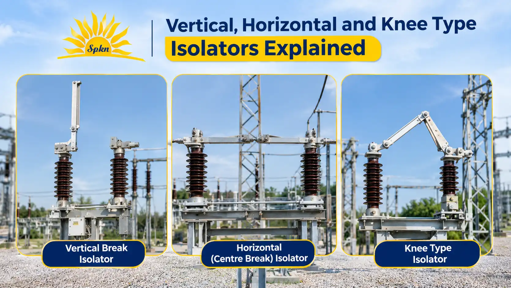
An isolator does one job: it gives a visible, safe break in a circuit so that people can work on equipment that is not live. But isolators do not all look the same or open the same way. The direction in which the blade moves decides how much space the isolator needs, how it is mounted and where it fits in a substation. This guide explains the three layouts that buyers meet most often, vertical break, horizontal (centre break) and knee type isolators, with a clear comparison so that you can pick the right one.
What an Isolator Does
An isolator, also called a disconnector, is a mechanical switch that opens a circuit when no load current is flowing. It is not designed to break load or fault current, which is the job of a circuit breaker. Instead, it creates a visible air gap so that maintenance staff can see that the equipment is cut off from the supply. Most isolators also have an earthing switch that connects the isolated section to earth for safety. If you want the basics first, read our guide on how isolators work in substations.
Why the Opening Direction Matters
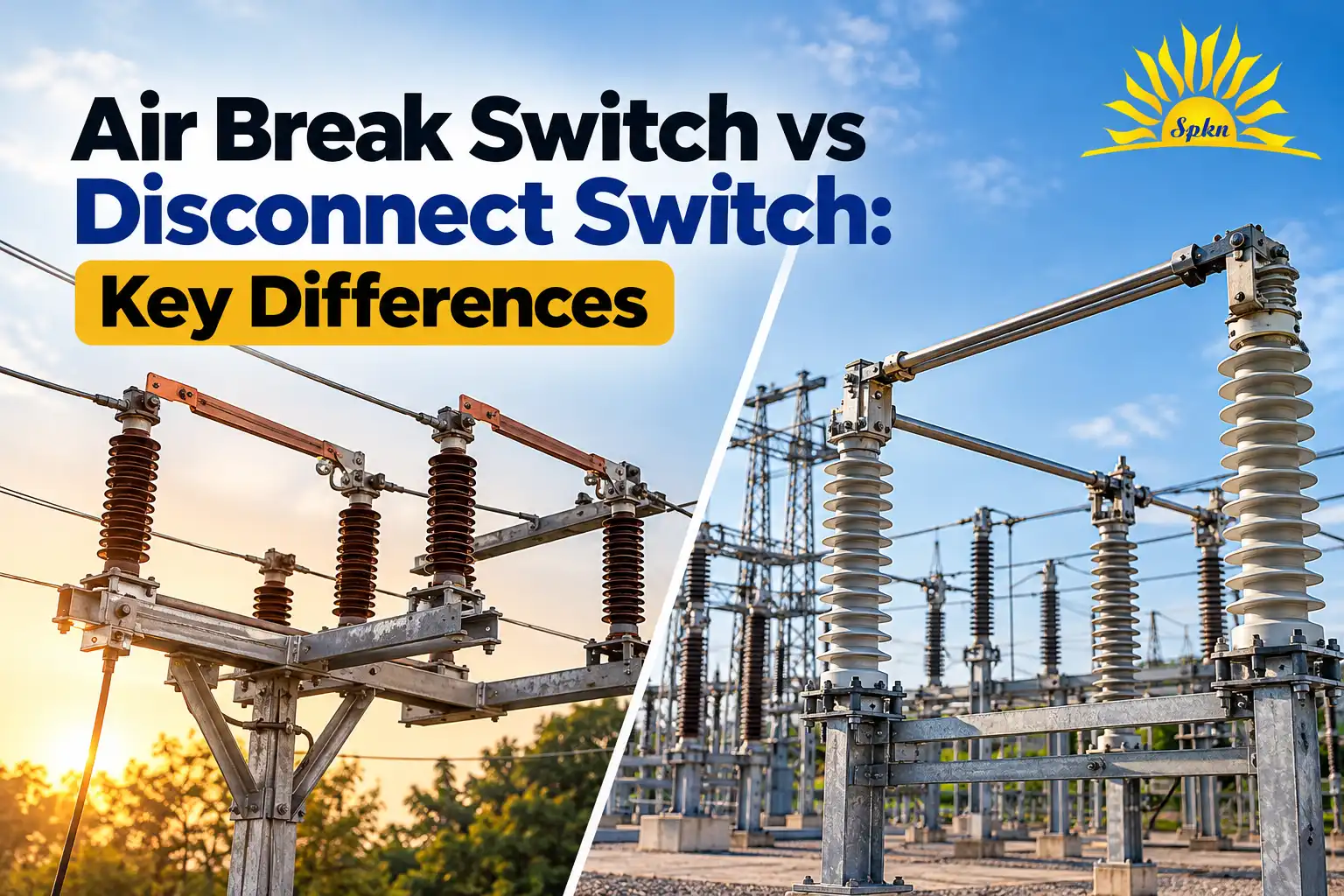
An outdoor substation has strict clearances between phases and to the ground. When the isolator opens, the moving blade sweeps through space. If that space is wide, the yard needs more land and more steel. If it is tall, the structure must be higher. The three layouts below trade width against height, and each also affects mounting, maintenance access and operating mechanism. Choosing the wrong layout can force a costly change to the bay design.
Horizontal (Centre Break) Isolator
How it works
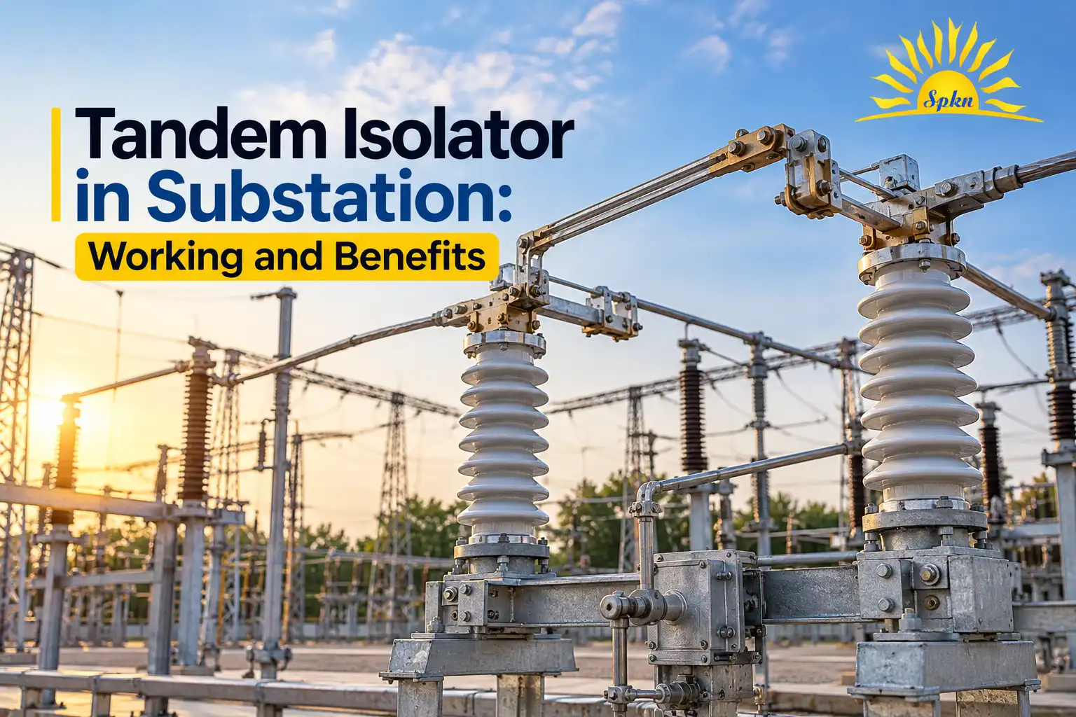
In a horizontal centre break isolator, there are two rotating insulator columns on each pole, with a blade arm mounted on top of each. The two arms meet at the centre when closed. To open, each column rotates, swinging its arm sideways in a horizontal plane so that the arms separate. The result is a double break, with two air gaps in series per pole.
Where it is used
This is the most common layout for outdoor isolators from 33 kV upward. It is used in main busbar sections, line bays and transformer bays, and it is a standard choice in many utility specifications. The double break gives a good insulation level across the open gap.
Strengths and weaknesses
- Strength: Proven design with a wide range of ratings, and easy to inspect from ground level.
- Strength: Low height, so the structure can be short.
- Weakness: The blades swing sideways, so the phase-to-phase spacing must be larger than for some other layouts.
Vertical Break Isolator
How it works
In a vertical break isolator, the blade opens in a vertical plane. It usually has a single break, and the blade lifts away from the fixed contact and rises upward. The mounting can be upright or underhung, depending on whether the base is above or below the contacts.
Where it is used
Vertical break isolators suit yards where the width between phases is limited but there is enough height. They are common where an isolator is installed directly under or over a busbar or conductor, because the blade does not sweep sideways into neighbouring phases. You can read more about the single and double break approach in our guide to single break and double break isolators.
Strengths and weaknesses
- Strength: Narrow phase spacing, so the bay can be compact in width.
- Strength: Fewer parts in the blade path, which keeps the mechanism simple.
- Weakness: The open blade extends upward, so there must be enough clearance above it to the next conductor or structure.
Knee Type Isolator
How it works
A knee type isolator has a contact arm that folds at a hinged joint when it opens, much as a leg bends at the knee. As the mechanism turns, the arm collapses toward the base and clears the fixed contact. Because the arm folds instead of swinging through its full length, the space it occupies when open is smaller.
Where it is used
This layout is used where both height and width are restricted, such as in compact or indoor-style outdoor yards, some industrial substations and bays with tight clearances. Different manufacturers use different names for similar folding designs, so always ask for the drawing and the clearance diagram, not just the name.
Strengths and weaknesses
- Strength: Compact open position, which saves space in both directions.
- Weakness: More hinges and joints in the current path, so contact and joint quality need careful checking.
- Weakness: Fewer suppliers and fewer standard ratings than the horizontal centre break design.
Side-by-Side Comparison
| Point | Horizontal (centre break) | Vertical break | Knee type |
|---|---|---|---|
| Blade movement | Rotates in a horizontal plane | Opens in a vertical plane | Arm folds at a hinge |
| Number of breaks | Double break | Usually single break | Usually single break |
| Width needed | Largest | Small | Small |
| Height needed | Low | Higher | Moderate |
| Typical use | Main yards, line and bus bays | Tight phase spacing | Compact bays |
| Range of ratings | Very wide | Wide | More limited |
This table is a general guide. Real isolators differ by manufacturer, so always compare the clearance drawings of the exact model.
How to Choose the Right Layout
- Start with the space. Measure the available width between phases and the height to the next conductor or structure. This often decides the layout before any other factor.
- Check the voltage and current rating. Make sure the model is available at your system voltage, rated current and short-time current rating.
- Check the insulation level. Confirm the withstand voltage across the open gap and to earth for your system.
- Decide the mounting. Choose upright or underhung and the type of base frame, according to the structure you have.
- Pick the operating mechanism. Select manual or motor operation, and decide whether an earthing switch is needed on one or both sides.
- Think about pollution. In dusty or coastal areas, choose a longer creepage insulator and plan regular cleaning.
- Compare maintenance access. Check how easily crews can reach the contacts, the mechanism and the bearings.
Ratings, Standards and Tests
Isolators are covered by IEC 62271-102, with matching Indian standards for alternating current disconnectors and earthing switches. Key ratings include the rated voltage, rated normal current, rated short-time withstand current and its duration, rated peak withstand current and the insulation level. Ask for type test reports and routine test reports, and for a mechanical endurance test report that shows the number of operations the design has passed. These tell you more than a catalogue photograph does. For ratings by voltage class, see our pages on the 33 kV substation isolator, the 66 kV substation isolator and the 220 kV outdoor isolator.
Operating Mechanism and Interlocking
The mechanism turns the movement of a handle or motor into the movement of the blade. A hand-operated gear box is simple and common at lower voltages, while higher voltage isolators usually use a motor drive with a local push button and a remote control option. In every case the mechanism should have clear open and closed indicators, a mechanical stop at each end of travel and a way to lock the isolator in position. Interlocks are essential. The isolator must not open or close while the breaker is closed, and the earthing switch must not close while the main blades are closed. Electrical and mechanical interlocks together give the best protection against operator error, which is the most common cause of serious isolator accidents.
Typical Bay Arrangements
In a line bay, the isolator usually sits between the line and the circuit breaker, so that the breaker can be isolated from the incoming line. In a transformer bay, isolators sit on either side of the breaker, so that it can be taken out for maintenance with a visible break on each side. In a busbar arrangement, bus isolators let a feeder be moved from one bus to another. The layout you choose must fit each of these positions without crowding the neighbouring bay, which is why drawings of the open position matter as much as the closed one. Our gantry structures and substation erection services can help plan and build the supporting steelwork.
Common Mistakes When Selecting Isolators
- Choosing by name only. A knee type from one maker may differ from a knee type from another. Check the drawing.
- Ignoring open-position clearance. The blade must stay clear of other phases and structures in the open position too.
- Forgetting the earthing switch. A missing or wrongly placed earth blade can force a rework in the bay.
- Underrating the short-time current. The isolator must carry the fault current through the protection clearing time without damage.
- Overlooking interlocks. The isolator must be interlocked with the breaker so it cannot be operated on load.
Maintenance Basics
All three layouts need the same basic care. Clean and inspect the insulators, check the contacts for burn marks and pitting, lubricate bearings and moving joints with the recommended grease, and operate the isolator by hand at least once a year to prove that it still moves freely. Check the alignment so that the blade enters the fixed contact smoothly, and check the interlocks and auxiliary switches. A well-aligned isolator also lasts longer, because misalignment wears the contacts and heats the joints. Connectors on the terminals deserve a check too; our substation connectors range covers common sizes.
Isolators From SPKN India
SPKN India manufactures outdoor isolators in several layouts and voltage classes at its works in Faridabad, along with the connectors, insulators and structures that go with them. See the full isolators range, and our guide on 11 kV vs 33 kV isolator selection. Send us your voltage, current rating, space limits and quantity, and we will recommend a layout and send an itemised quotation. You can also call +91 9999501843.
Get a Free Quote from SPKN India WhatsApp Us