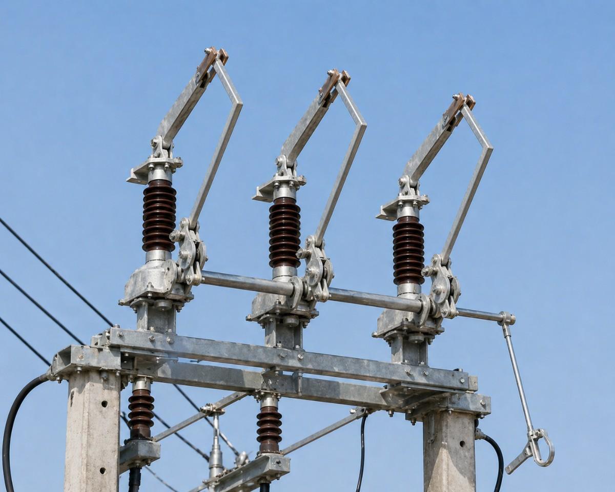
33 kV Air Break Switch: Ratings, Specifications and Buying Guide
A 33 kV air break switch is the standard device for sectionalising and isolating overhead lines in the sub-transmission network. It sits between the grid substation and the 11 kV distribution system, on lines that feed town substations, industrial plants and solar or wind farms. Because a 33 kV line carries a lot of power over several kilometres, a mistake in specifying the switch can leave thousands of consumers without supply or put a lineman at risk.
This page is a buying and specification guide for the 33 kV class. It covers the ratings used in India, the insulation and creepage values that matter, the design choices between types, installation points and a checklist for tenders. If you want a general explanation of how an air break switch works, read our page on the air break switch first.
Where a 33 kV Air Break Switch Is Used
- 33/11 kV substation incomers, so the transformer bay can be isolated from the incoming line.
- Tap-off points where a branch line leaves the main 33 kV feeder to a factory or a village substation.
- Feeder sectionalising on long lines, so a fault section can be isolated and the healthy part restored.
- Renewable energy plants where the pooling substation connects to the grid line.
- Industrial plants that take supply at 33 kV and need a visible point of isolation at the boundary.
Standard Ratings for 33 kV Class
| Parameter | Usual value for 33 kV |
|---|---|
| Highest system voltage | 36 kV |
| Power frequency withstand voltage | 70 kV |
| Lightning impulse withstand voltage | 170 kV peak |
| Rated normal current | 400 A, 630 A, 800 A or 1250 A |
| Short-time withstand current | 16 kA, 20 kA or 25 kA for one second, as per fault level |
| Frequency | 50 Hz |
| Number of poles | Three |
These are common values. The fault level at your site, which the utility can provide, decides the short-time rating. Choosing a lower value than the fault level is unsafe, because the contacts can weld or the structure can be damaged during a fault.
Creepage Distance and Pollution
The insulators on the switch are the part most exposed to the weather. Dust, salt, cement and industrial smoke settle on their surface and form a conductive layer when it is damp. Creepage distance is the length of the surface path from the live part to earth. For a 36 kV system, the creepage required rises with pollution:
- Light pollution: about 580 mm.
- Medium pollution: about 720 mm.
- Heavy pollution: about 900 mm.
- Very heavy pollution: about 1,120 mm.
These values follow the 16, 20, 25 and 31 mm per kV guidance in IEC 60815. If the switch will stand near a coast, a cement plant or a chemical factory, ask for a higher creepage or polymer insulators. Our pages on porcelain insulators and polymer insulators explain how the two materials behave.
Design Choices at 33 kV
Centre-break or double-break
Most 33 kV switches in India use the horizontal centre-break design, where two blades rotate and meet at the middle of each pole. The gap in the open position is wide and easy to inspect. Double-break designs suit tighter yards and heavier duty.
Operation: manual, gang or motorised
Manual gang operation through a ground-level handle is the standard choice. A motorised mechanism adds remote operation and is useful where the switch is far from the substation or is operated often. Motor-operated switches need an auxiliary supply and a local manual override for emergencies.
Earth switch
An earth switch on one or both sides lets the isolated line be grounded before work starts. It is interlocked with the main blades so the two cannot be closed together by mistake. For tender purposes, state clearly whether you need no earth switch, one or two.
Arcing horns
Arcing horns allow the switch to break small load and charging currents. If your use includes switching an unloaded transformer or a short line, specify them and ask for the rated breaking current.
Why 33 kV Lines Need Their Own Switching Points
A 33 kV line is a link in the middle of the network. It brings bulk power from a 132 kV or 66 kV grid substation to many smaller 33/11 kV substations, and each of those feeds hundreds of consumers. When a fault happens on a long 33 kV line, the breaker at the source trips and the whole line goes dead. Without sectionalising switches, the utility has to patrol the full length to find the fault before restoring supply. With air break switches placed every few kilometres, the crew can open the switches on either side of the suspected section, close the breaker, and restore power to the healthy parts while they repair the faulty one.
This is why utilities place switches at tap-off points, at the boundary between rural and urban sections, and on either side of long river or railway crossings. Each switch shortens the outage time for the consumers connected beyond it.
Air Break Switch, Isolator, Breaker or Recloser: Which One Where
| Device | Interrupts fault current | Typical role on a 33 kV line |
|---|---|---|
| Air break switch | No | Visible isolation and sectionalising |
| Isolator in a substation bay | No | Isolates equipment such as a breaker or transformer |
| Circuit breaker | Yes | Protects the line and clears faults |
| Recloser | Yes, with automatic reclosing | Handles temporary faults on long rural feeders |
An air break switch gives the visible gap that crews need for safety, and the breaker or recloser provides the protection. They are used together, not as substitutes. Our guide on isolator versus circuit breaker explains the split in detail.
Worked Example: Choosing a Switch for a Tap-Off Line
Take a 33 kV feeder that supplies a new 5 MVA industrial substation through a tap-off line. The full load current at 33 kV is about 5,000 kVA divided by 1.732 times 33 kV, which is roughly 87 A. Allowing for growth to 10 MVA and for overload, a 400 A switch is more than enough, and a 630 A rating gives a comfortable margin. The fault level at the tap-off point, taken from the utility, is 18 kA. The next standard rating above that is 20 kA for one second, so the switch should be rated 36 kV, 630 A, 20 kA. The site is 15 kilometres from the coast, so a medium to heavy pollution class applies and the creepage should be about 900 mm. The result is a clear, written specification that any supplier can quote against, which makes the comparison fair.
Clearances and Safety Signs
Electrical rules set minimum clearances between live parts and the ground, and between phases. The structure must keep these distances in the open and closed positions, including when the blades are swinging. The operating handle should be at a height that the operator can reach without a ladder, and a platform or insulating mat should be provided where required. Fit a danger board with the voltage on the structure, and lock the handle when the switch is not in use. Keep the area around the structure free of vegetation and climbing aids so that unauthorised persons cannot approach the live parts.
Specification Checklist for a Tender
- Rated voltage 36 kV, three-pole, outdoor, 50 Hz.
- Rated current and short-time current with duration.
- Insulation level and creepage distance, with the pollution class at site.
- Type of insulator: porcelain or polymer, with the standard it conforms to.
- Operating mechanism, including handle height and interlocks.
- Earth switch requirement.
- Structure and fasteners: hot-dip galvanised to the thickness specified.
- Test reports: type tests for temperature rise, short-time current and dielectric strength, and routine tests for each unit.
- Applicable standards: IS 9921 and IEC 62271-102 for disconnectors and earthing switches.
Installation Notes
Mount the switch on a rigid steel structure or on a pair of poles with cross-arms, at a height that keeps the lowest live part clear of the ground as the rules require. Align the poles with a level, and operate the switch a few times with the line dead to confirm that all three blades close together. Connect the line with clamps rated for the conductor, such as our substation connectors, and earth the frame and handle with a short, thick conductor. Put a lightning arrester near the line entry to protect the switch and the equipment behind it.
At a 33/11 kV substation, the switch is only one part of the incoming bay. See our guide to a power substation for how the isolator, breaker, transformer and arrester fit together. For a version with a motor drive and a fixed mounting on a gantry, our 33 kV substation isolator page lists the range.
Maintenance Plan
- Visual inspection every six months for cracked insulators, loose bolts and rust.
- Clean insulators before the monsoon and after the dry season in polluted areas.
- Check contact pressure and surface condition once a year, and polish or replace worn parts.
- Lubricate bearings and the operating mechanism on schedule.
- Thermal scan during peak load to find hot spots at clamps and contacts.
Common Mistakes When Buying a 33 kV Switch
- Choosing a 24 kV or 12 kV switch because it is cheaper. A 33 kV system needs a 36 kV rating.
- Ignoring the fault level and picking the short-time rating from habit.
- Accepting a thin galvanising layer that will rust within a few years.
- Not checking creepage distance for a polluted site.
- Buying without type test reports for the exact design.
Supply From a Faridabad Manufacturer
SPKN India makes 33 kV air break switches and other high-tension equipment in Faridabad and delivers across India. Send us your rated current, fault level, pollution class, mechanism preference and quantity, and we will prepare a technical offer. You can also call +91 9999501843.