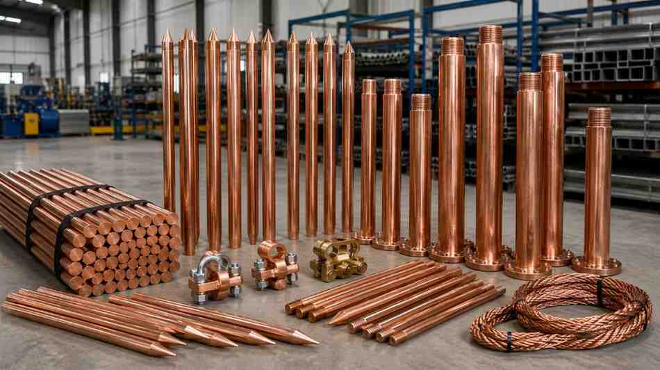
Earthing Electrode Manufacturers in India: What to Look For Before You Buy
An earthing system is the part of an installation that nobody notices until a fault or a lightning strike tests it. At that moment the earthing electrode decides whether the fault current flows safely into the ground or through a person, a motor or a control panel. That is why buyers who search for earthing electrode manufacturers in India should look past the price and ask how the electrode is made, tested and installed.
This guide explains what an earthing electrode does, the main types sold in India, how to choose between them, and how to judge a manufacturer. It is written for plant engineers, electrical contractors and purchase teams who specify earthing for substations, factories, buildings and solar plants. SPKN India is a Faridabad-based manufacturer of high-tension electrical equipment, and earthing is part of almost every project we supply.
What an Earthing Electrode Does
An earthing electrode is the metal part buried in the ground that connects an electrical system to the earth. It has three jobs. It carries fault current away so that protective devices trip quickly. It keeps exposed metal parts at a safe voltage so that nobody receives a dangerous shock. It also gives surge currents from lightning a low-resistance path to ground, which protects transformers, cables and lightning arresters from damage.
The performance of the whole system is measured by earth resistance, expressed in ohms. A lower value means the electrode can pass current into the soil more easily. The target depends on the installation, and IS 3043, the Indian code of practice for earthing, is the usual reference.
Earth Resistance Targets for Common Installations
Design targets differ with the size and risk of the installation. The values below are commonly applied figures. Always confirm the exact limit with your design engineer and the local electricity authority.
| Installation | Commonly applied target |
|---|---|
| Large power station | About 0.5 ohm |
| Major substation | About 1 ohm |
| Small substation | Up to about 2 ohm |
| Industrial and building earthing | As set in the design and local rules |
Main Types of Earthing Electrodes in India
Galvanised iron (GI) pipe electrodes
GI pipe is the traditional choice. A pipe of 40 mm to 50 mm diameter is driven or buried vertically, often with a funnel on top for watering. It is inexpensive and widely understood. Its weakness is corrosion: once the zinc coating wears away, the steel rusts and the resistance rises. It needs regular watering and inspection, so it suits low-cost installations with a maintenance routine.
Copper bonded rods
A copper bonded rod has a high-strength steel core with a thick layer of copper bonded to it. The steel gives the strength to drive the rod deep, and the copper gives long life and good conductivity. These rods can be coupled to reach deeper, wetter soil layers, which helps in dry or rocky ground. They are common in substations, telecom sites and solar plants.
Solid copper electrodes
Solid copper rods and plates have the best conductivity and corrosion resistance, but they are expensive and attractive to thieves. They are used where the budget allows and where the earthing must last for decades with very little deterioration.
Chemical and maintenance-free electrodes
A chemical electrode is a hollow copper or GI tube filled with a salt-based compound that releases moisture slowly into the surrounding soil. This lowers the resistance in dry or rocky soil and keeps it stable across seasons. Quality varies a lot between products, so ask what the filling compound is and how long it is expected to last.
Earthing plates and strips
Plates, usually GI or copper, are buried flat in a pit with charcoal and salt layers. Strips and earth mats are laid horizontally to build a grid under a substation yard. These do not replace vertical electrodes. They work together with them to spread the current over a wide area.
Earthing Electrode Types Compared
| Type | Corrosion resistance | Maintenance | Typical use |
|---|---|---|---|
| GI pipe | Moderate | Regular watering and checks | Low-cost building and industrial earthing |
| Copper bonded rod | High | Low | Substations, telecom, solar plants |
| Solid copper | Very high | Very low | Critical installations |
| Chemical electrode | High | Low, check compound life | Dry or rocky soil |
| Plate and strip | Depends on material | Depends on design | Earth grids, pit earthing |
How to Choose the Right Electrode
Start with the soil. Soil resistivity changes with moisture, salt content and rock, and it can differ widely between two sites only a few kilometres apart. A soil resistivity test, usually done by the Wenner four-pin method, tells the designer how deep and how many electrodes are needed. After that, work through four questions.
- What fault current must the system carry? The conductor and electrode must take it for the full clearing time without overheating.
- What is the soil like? Dry sand, rock and laterite need deeper or chemical electrodes. Moist clay is easier.
- How long must it last? A design life of 25 years points to copper bonded or copper, not bare steel.
- Who will maintain it? If nobody will water or inspect the pit, choose a maintenance-free design.
Sizing the Earthing Conductor
The electrode is only one part of the path. The conductor that joins it to the equipment must also carry the full fault current for the time the protection takes to clear it, without melting or losing strength. Its cross-section is therefore worked out from the system fault level and the relay clearing time, with a margin for corrosion over the years. Using a thinner strip than the calculation asks for is a false economy, because the first serious fault can burn it open and leave the equipment unearthed at the worst moment. Keep joints to a minimum, and make each one with a bolted clamp rated for the current or a proper weld.
What a Good Earthing Electrode Manufacturer Offers
- Clear material data. Copper thickness on bonded rods, zinc coating on GI items and wall thickness on pipes should be stated and measurable.
- Test records. Coating thickness, tensile strength and dimensions should be checked on every lot, with reports available.
- Standards compliance. Ask which IS or IEC standard applies, for example IS 2629 for hot-dip galvanising, and request proof.
- Accessories. Clamps, couplers, driving studs, test links and inspection chambers should come from the same supplier so they match the electrode.
- Technical support. A manufacturer who can advise on pit layout and resistance targets saves rework.
- Dependable delivery. Projects stall when earthing material arrives late, so ask about lead time and stock.
Installation Practices That Protect Performance
A good electrode can still give poor results if it is installed badly. Drive vertical rods to the full designed depth and keep a spacing of at least twice the rod length between neighbouring electrodes, so that they do not share the same zone of soil. Make joints with proper clamps or exothermic welds, not twisted wire. Protect underground joints from corrosion and seal them well. Connect every pit to the main earth grid with a conductor sized for the fault current, and bring a test point above ground so that resistance can be measured without digging.
After installation, measure the earth resistance by the fall-of-potential method, and record the value. For the full picture of how an earth grid fits into a substation, read our guide to the power substation, and for erection support see our substation erection services.
Maintenance Schedule
- Every year: measure the resistance of each pit and the whole system, ideally at the end of the dry season when the value is highest.
- Every year: check clamps, bolts and visible conductors for corrosion and looseness.
- After a major fault or lightning strike: inspect the nearby pits and re-test.
- For GI pipe and plate earths: water the pit as the design requires and refresh the salt and charcoal if needed.
- For chemical electrodes: follow the manufacturer's advice on compound life and replacement.
Earthing and Lightning Protection Work Together
A lightning arrester diverts a surge to ground, but it can only do its job if the earth path is low in resistance and short. Keep the earth lead from the arrester as straight and short as possible. Our guides on lightning arrester installation and the lightning arrester for a building explain where the earthing connection goes in each case. Equipment bonded to the same earth grid, including isolators and connectors, should use fittings rated for the fault current. See our substation connectors for compatible hardware.
Common Mistakes With Earthing Electrodes
- Choosing by price alone and ending up with thin copper coating or a poor zinc layer.
- Skipping the soil resistivity test and guessing the number of electrodes.
- Placing electrodes too close together, which wastes their effect.
- Using different metals in one system without protecting the joints, which causes galvanic corrosion.
- Never measuring the resistance again after commissioning.
- Connecting separate earths for power, lightning and instruments without a planned bond between them.
Pit Earthing or Rod Earthing: Which Is Better
Pit earthing buries a plate or pipe in a pit filled with charcoal and salt layers. Rod earthing drives one or more rods straight into the ground. Pit earthing works where land is soft and the water table is reasonable, and it has been used in India for decades. Its resistance depends on the pit being kept moist and the filling being intact. Rod earthing, especially with copper bonded rods, reaches deeper layers that stay wet in every season, so its value is steadier. For a substation or a plant with high fault levels, most designers combine both: vertical rods at the corners and along the grid, joined by buried strip. For a small building, a single maintained pit with a test link may be enough. Match the choice to the fault level, soil and maintenance capacity, not to habit.
Choosing Earthing From a Faridabad Manufacturer
SPKN India supplies earthing electrodes and related high-tension equipment to utilities, contractors and industry across India. Share your soil data, target resistance, fault level and quantity, and we will recommend the electrode type and prepare an itemised quotation. You can also call +91 9999501843.