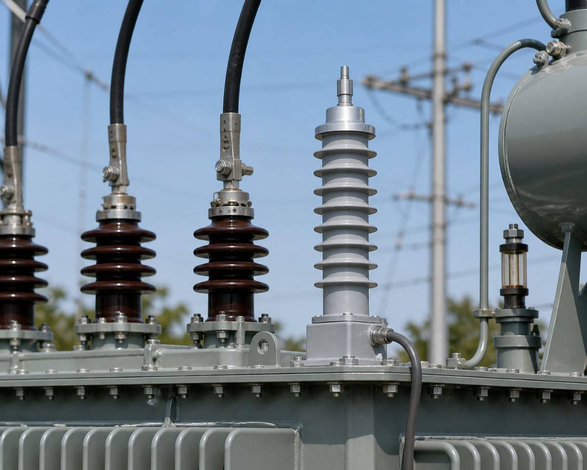
Lightning Arrester in Transformer: How It Protects and Where It Is Fitted
A transformer is among the costliest and most important items in an electrical network, and it is also one of the most sensitive to surges. Its windings are insulated for the system voltage with a margin, but a lightning or switching surge can be many times higher than that. When the surge is larger than the insulation can stand, it punctures the paper and oil between winding turns, and the transformer fails, often with an internal fault that cannot be repaired on site. A lightning arrester fitted at the transformer bushings is the standard defence.
This guide explains how a lightning arrester protects a transformer, how the arrester and the transformer insulation work together, where to fit the arresters, which ratings suit each voltage class, and what mistakes to avoid. It is written for utility engineers, contractors and plant electricians. For the selection of an 11 kV arrester specifically, see our page on 11 kV lightning arresters.
Why Transformers Need Surge Protection
A transformer winding has inductance and capacitance. A fast surge does not spread evenly along the winding. Most of its voltage appears across the first few turns near the line terminal, and the stress there can be many times that of normal operation. The insulation on these turns is the part that fails first. The design standard sets a basic insulation level (BIL), the surge voltage the transformer must withstand in a test. The arrester's job is to keep the surge at the transformer terminal well below that BIL.
How the Arrester Protects the Transformer
The arrester connects between each phase terminal and earth. In normal service it draws only a tiny leakage current. When a surge arrives, the arrester starts to conduct, takes the surge current to earth and holds the voltage at the terminal to a value called the residual voltage. After the surge passes, it returns to its non-conducting state. The transformer sees a surge limited to the residual voltage plus a small allowance for the lead length, which is far below its BIL.
Insulation Coordination in Plain Words
Insulation coordination means arranging the arrester rating and the equipment insulation so that the arrester always operates before the transformer is stressed. In practice you compare three numbers: the BIL of the transformer, the residual voltage of the arrester at its discharge current, and the voltage added by the connecting leads. A protective margin of at least 20 percent is the common minimum, and 40 percent or more is better. The table shows the standard BIL values for common voltage classes.
| System voltage | Highest system voltage | Transformer BIL (lightning impulse) | Common arrester rated voltage |
|---|---|---|---|
| 11 kV | 12 kV | 75 kV | 9 kV or 12 kV |
| 33 kV | 36 kV | 170 kV | 27 kV or 30 kV |
| 66 kV | 72.5 kV | 325 kV | 60 kV |
| 132 kV | 145 kV | 550 kV | 120 kV |
| 220 kV | 245 kV | 950 kV | 198 kV |
The rated voltage depends on how the system neutral is earthed. The values above suit effectively earthed systems. Always confirm with the utility or the design engineer.
Where to Fit the Arresters
On the high-voltage side
Fit one arrester on each phase, as close as possible to the HV bushing. On pole-mounted distribution transformers, the arrester is often mounted on the same cross-arm or on a bracket on the pole, directly above the transformer. In a substation, arresters are mounted on a support next to the transformer, and the connection is made with short, straight leads.
On the low-voltage side
Surges can also arrive from the LV network, or through the transformer by capacitive coupling. For important transformers, LV arresters or surge protective devices are installed on the LV bushings. This is less common on small pole-mounted units but more common for transformers feeding sensitive loads.
On the neutral
On large power transformers with a neutral that is not solidly earthed, an arrester on the neutral protects the neutral bushing from surges that appear when the system is operating with unbalanced faults.
Lead Length and Earth Connection
During a surge, current rises extremely fast, and even a short lead has enough inductance to add a large voltage. As a rough guide, each metre of lead can add 1 kV or more in a fast surge. This voltage adds to the arrester's residual voltage and reaches the transformer. Keep the line lead and the earth lead short, thick and straight, with no loops. Connect the arrester earth directly to the transformer tank and to the main earth electrode, so that the arrester, the transformer tank and the earth are at the same potential during the surge. Our guide to earthing electrodes shows how to keep earth resistance low, and our page on lightning arrester installation gives the steps.
Worked Example: Protective Margin for a 33/11 kV Transformer
Consider a 33/11 kV, 5 MVA power transformer, with a 33 kV BIL of 170 kV. The utility chooses a 30 kV, 10 kA metal oxide arrester on the 33 kV side. The data sheet gives a residual voltage at 10 kA of about 80 kV. The arrester is mounted on a stand about 2 metres from the bushing, and the lead and earth path adds around 3 kV per metre of total conductor in a fast surge, so about 6 to 8 kV extra. The voltage at the transformer terminal is then about 88 kV. The protective margin is 170 divided by 88, which is about 1.9, or a margin of 90 percent over the surge level. This is a healthy figure. If the arrester were moved 10 metres away, the extra voltage could reach 30 kV or more and the margin would fall to about 1.4. It would still be acceptable on paper, but real surges are more complex than the simple calculation, so shorter leads are always better.
Arrester Failure Modes and What They Mean
An arrester at the end of its life usually fails as a short circuit to earth. The line then trips, or the disconnector on the earth lead operates and drops away. Occasionally the housing cracks or tracks over the surface from pollution. Warning signs include a rising leakage current in routine tests, a hot spot on a thermal scan, a cracked housing or a disconnector that has dropped. An arrester that has taken a heavy surge may also show no outward sign but have damaged blocks, so after a known direct strike the arresters near the point of impact should be checked. A failed arrester should be replaced at once, since the transformer is unprotected until it is.
Arresters on Different Transformer Types
| Transformer | Arrester practice |
|---|---|
| Pole-mounted distribution transformer (11/0.415 kV) | Three polymer 5 kA or 10 kA arresters on the HV side, mounted at the bushings |
| Plinth or ground-mounted distribution transformer | Arresters on the HV bushings, often with a cable end arrester if fed by cable |
| 33/11 kV power transformer in a substation | Arresters on both 33 kV and 11 kV sides, 10 kA class |
| 66 kV and 132 kV transformers | Arresters on each HV phase and on the neutral where required, 10 kA or 20 kA |
| Transformers fed by cable | Arresters at the cable end, where surges reflect and double |
Types of Arresters Used With Transformers
- Metal oxide arresters are the standard choice for new work. They have no gap, respond fast and give low residual voltage. They follow IS 3070 Part 3 and IEC 60099-4.
- Polymer-housed arresters are common on pole-mounted transformers because they are light and fail safely.
- Porcelain-housed arresters are common in substation yards.
- Older gapped and horn gap arresters are still found in old networks. Our page on the horn gap explains where they remain useful.
Selection Steps for a Transformer
- Note the transformer voltage class, kVA or MVA rating and BIL.
- Find out how the system neutral is earthed, and select the arrester rated voltage and MCOV accordingly.
- Choose the discharge current: 5 kA or 10 kA for distribution, 10 kA or 20 kA for substation and power transformers.
- Check the residual voltage in the data sheet and calculate the protective margin against the BIL.
- Select the housing and creepage distance for the site pollution.
- Plan the mounting position, line lead and earth lead to keep the lead length short.
- Ask for the type test and routine test reports.
Do Arresters Replace the Need for Earthing and Shielding?
No. An arrester limits the voltage that reaches the transformer, but it works only as well as the earth path behind it. A substation also needs shield wires or masts to intercept direct strikes, and good bonding between the arrester, the tank and the earth grid. Treat the arrester, the earth and the shielding as one protection system, and check all three whenever a transformer is installed or replaced.
Inspection and Testing Routine
- Before every monsoon: inspect all arresters on transformers for cracks, tracking and loose connections.
- Every year or two: measure leakage current with a clamp-on tester or a thermal scan, and compare each phase with the others.
- After a lightning storm: check for dropped disconnectors and flashover marks on nearby arresters.
- At transformer maintenance: test earth resistance and inspect the earth lead and connections.
- Keep records: note serial numbers, dates and test values so that ageing trends are visible over the years.
Common Mistakes
- Mounting the arrester far from the transformer, with long leads that remove most of the protection.
- Choosing the arrester rating without checking the neutral earthing.
- Connecting the arrester earth to a separate earth pit instead of the tank and the main earth.
- Protecting only one or two phases.
- Leaving a failed arrester on the line after its disconnector has operated.
Arresters for Transformer Protection From SPKN India
SPKN India is a Faridabad-based manufacturer of high-tension equipment, including lightning arresters. Send us your voltage class, transformer rating, neutral earthing and quantity, and we will prepare a technical offer. See our lightning arresters page for the range. You can also call +91 9999501843.