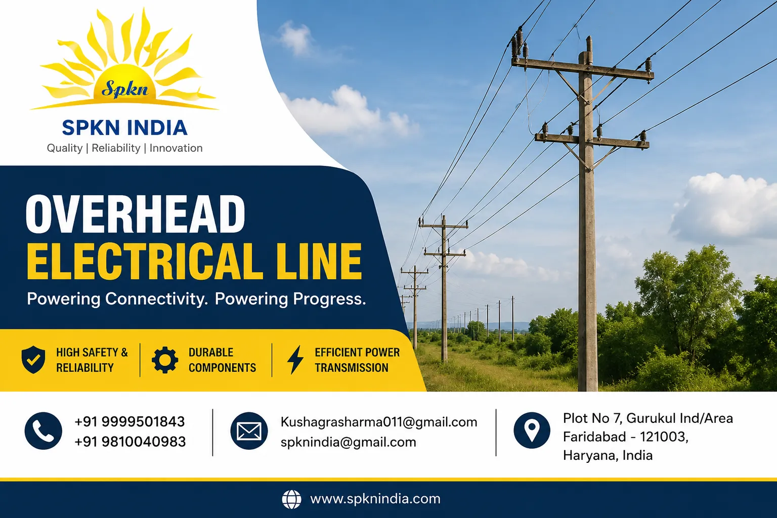
Overhead Electrical Line: Components, Types, Clearances and Maintenance
An overhead electrical line is a set of conductors strung on poles or towers to carry electricity through the air. It is the most common way to bring power to villages, towns and factories in India. Look along any road and you will see them: low-voltage lines to houses, 11 kV feeders along main roads, and 33 kV lines running towards a substation. Compared with underground cable, an overhead line is cheaper, quicker to build and easier to repair, which is why it carries most of the distribution load in the country.
This guide explains the parts of an overhead electrical line, the types used at different voltages, the clearances and spacing that keep it safe, how it is built and maintained, and how it compares with underground cable. It is written for utility engineers, contractors and anyone planning a new connection.
Main Parts of an Overhead Electrical Line
| Part | Role |
|---|---|
| Poles or towers | Hold the conductors at a safe height |
| Cross-arms | Carry the insulators and set the spacing between phases |
| Conductors | Carry the current |
| Insulators | Separate the live conductor from the pole and cross-arm |
| Stay wires and struts | Balance the pull of conductors at corners and line ends |
| Earth wire and earthing | Protect against lightning and faults |
| Fuses, switches and arresters | Protect and sectionalise the line |
Types of Overhead Lines by Voltage
Low-voltage (LT) lines
At 230 V or 415 V, these lines bring power from the distribution transformer to homes and shops. They use bare aluminium conductors or insulated aerial bunched cable, on poles about 8 to 9 metres tall, with spans of 30 to 50 metres.
11 kV and 22 kV lines
These are the primary distribution feeders. They carry power from a substation to many pole-mounted transformers. The conductors are bare ACSR or AAAC, mounted on pin or disc insulators, on poles 9 to 12 metres tall, with spans of 50 to 80 metres in towns and longer in open country.
33 kV lines
These sub-transmission lines link grid substations to town and industrial substations. They use heavier conductors, longer insulators and taller poles or small lattice towers, with spans of 100 to 200 metres.
66 kV and 132 kV lines
Built on steel poles or lattice towers with disc or polymer insulator strings. At these levels the design resembles the transmission lines covered in our guide to high voltage power transmission lines.
Types of Poles
- Wooden poles: rare today, used in some rural low-voltage lines.
- Prestressed concrete (PCC) poles: durable, cheap, and common for LT and 11 kV lines.
- Tubular steel poles: strong and light, suited for 33 kV and 66 kV, and for areas where concrete poles are hard to transport.
- Rail poles and lattice poles: used where extra strength is needed.
- Lattice towers: galvanised steel for 66 kV and above, and for long spans and crossings.
Conductors on Overhead Lines
Most overhead lines use aluminium conductors, with a steel core where strength is needed. ACSR sizes such as Rabbit, Dog and Panther are common on 11 kV and 33 kV lines, while AAAC is used near the coast. Covered conductors are used in tree-lined or hilly areas where branch contact is a concern. For the full range, read our guide to transmission line conductor types and our page on the conductor in a transmission line.
Insulators for Overhead Lines
Pin insulators hold the conductor on straight runs at 11 kV and 33 kV. Disc and long rod insulators carry the pull at corners, dead ends and higher voltages. Polymer insulators are light and good in polluted areas. See our pages on overhead line insulators, 11 kV polymer pin insulators and porcelain electrical insulators for details.
Clearances and Spacing
Safe clearances protect the public and keep the line reliable. They are set in the electricity safety regulations and depend on voltage and location. Three kinds of distance matter.
- Ground clearance: the minimum height of the lowest conductor above the ground, higher across roads and railways.
- Phase spacing: the distance between conductors on the cross-arm, wide enough to prevent contact when wind makes them swing.
- Clearance to buildings and trees: a horizontal and vertical distance that must be kept clear, so that a person on a roof or a ladder cannot reach the line.
Always check the current regulation and your utility's rules before you plan a line, because values change with voltage and with the type of area crossed.
Sag and Span
A conductor hung between two poles curves downward in a shape called a catenary. The sag is the vertical drop from the support to the lowest point. It grows with the square of the span and falls with higher tension. On a hot day the conductor expands and sags more, while in cold weather it tightens. Designers choose the span and tension so that the line keeps the ground clearance on the hottest day and does not overstress the poles on the coldest. A longer span needs fewer poles, but it needs taller poles and a stronger conductor.
Worked Example: Calculating Sag
For a level span, sag is approximately the conductor weight per metre times the span squared, divided by eight times the tension. Take a Dog ACSR conductor that weighs about 0.4 kg per metre on a span of 80 metres, with a working tension of 1,000 kg. The sag is 0.4 times 80 times 80, which is 2,560, divided by 8 times 1,000, which is 8,000. The sag comes to about 0.32 metres. For an 11 kV line, a small sag like this on a short span means the conductor stays nearly level, and ground clearance depends mainly on pole height. On a 200 metre span with the same weight and a tension of 1,000 kg, the sag becomes 0.4 times 40,000, which is 16,000, divided by 8,000, giving 2 metres. This shows that sag grows with the square of the span: a span 2.5 times longer gives a sag more than six times larger at the same tension, which is why longer spans need stronger poles, higher tension or taller supports.
Pole Loading and Stays
A pole does not only carry the weight of the conductors. At a corner or a line end, the conductors pull sideways, and wind pushes against both the conductors and the pole. A stay wire running from the top of the pole to an anchor in the ground balances this pull. The stay must be at the right angle, usually about 45 degrees, with an anchor deep enough to hold in the local soil. A stay insulator is placed in the wire above head height to stop a live conductor from energising the stay. Poles at corners and ends often need a double stay or a strut. Missing or loose stays are a frequent cause of leaning poles after a storm.
Choosing the Right Line for a New Connection
| Situation | Suggested line type |
|---|---|
| Rural village, open land, long route | Bare overhead line on PCC poles |
| Wooded or hilly route with many branches | Covered conductor on poles |
| Dense town with narrow streets | Aerial bunched cable or underground cable |
| Industrial plant needing 33 kV supply | 33 kV overhead line on steel poles or short towers |
| Crossing a railway or airport | Underground cable or a special tall crossing tower |
Aerial Bunched Cable and Covered Conductors
In crowded streets, bare wires are a risk to people and prone to theft and tree faults. Aerial bunched cable (ABC) twists insulated conductors together on a bearer wire. It takes less space, allows closer pole spacing and reduces outages from contact. Covered conductors on 11 kV and 33 kV lines work on the same principle but with a thinner layer. Both cost more than bare wire, so utilities use them where the risk is highest. Whatever the type, they must still be treated as live, because the insulation protects against brief contact only.
Protection and Switching on Overhead Lines
- Drop-out fuses protect transformers and branch lines. See our fuse switch guide.
- Air break switches isolate sections of line for maintenance. Read about the air break switch.
- Lightning arresters protect transformers and cable terminations from surges. See 11 kV lightning arresters.
- Reclosers and sectionalisers restore supply after temporary faults on rural feeders.
Overhead Line vs Underground Cable
| Point | Overhead line | Underground cable |
|---|---|---|
| Initial cost | Lower | Much higher |
| Construction time | Short | Longer |
| Fault finding and repair | Easy to see, quick to repair | Needs testing equipment, slower |
| Exposure to weather and trees | High | Low |
| Appearance and land use | Visible, needs clearance | Hidden, needs trench route |
| Typical use | Rural and suburban, long routes | Dense cities, crossings, airports |
Construction Steps
- Survey the route, mark pole positions and get permissions for the right of way.
- Dig pits and erect the poles with the correct depth and foundation.
- Fix cross-arms, insulators and stay sets.
- String the conductors, set the tension and sag, and fix the clamps.
- Install earthing, fuses, switches and arresters.
- Test insulation and earth resistance, then inspect and energise the line.
Maintenance and Common Faults
- Trim trees along the route before every monsoon.
- Replace cracked or flashed insulators and tighten loose clamps.
- Check pole bases for rot, rust or erosion, and re-set leaning poles.
- Scan joints with a thermal camera under peak load.
- Replace broken or corroded stay wires.
- Patrol the line after storms and floods.
Safety Rules
Treat every overhead line as live. Keep ladders, cranes, pipes and kites well away from it. Do not climb a pole without authority and a permit. If a conductor falls, keep clear and call the utility. For work on the line, isolate, test and earth it, then lock the switch, as explained in our guide to high tension wires.
Equipment for Overhead Lines From SPKN India
SPKN India is a Faridabad-based manufacturer of equipment used on overhead lines, including air break switches, insulators, lightning arresters and connectors. Send us your voltage, line type and quantity, and we will prepare a technical offer. You can also call +91 9999501843.