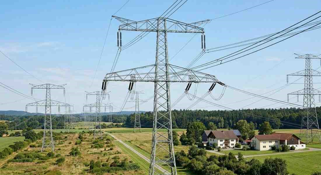
Understanding high transmission line voltage helps you make sense of everything from national grid planning to the equipment choices made at substations and industrial facilities. This guide breaks it all down clearly, practically, and without unnecessary complexity.
What Is High Transmission Line Voltage?
High transmission line voltage refers to the use of elevated voltage levels, typically starting at 66 kV and going up to 765 kV or beyond, to move bulk electrical energy across long distances from generating stations to load centres.
In India, the standard transmission voltage levels used by Power Grid Corporation of India (PGCIL) and state transmission utilities include 66 kV, 110 kV, 132 kV, 220 kV, 400 kV, and 765 kV. Some ultra-high voltage (UHV) research corridors are already exploring 1200 kV transmission in India, making the country one of the few in the world operating at that scale.
The core reason for using such high voltages is physics. And once you understand the logic, it is hard to argue with.
Why Is Electricity Transmitted at High Voltage?
This is the question most people ask first, and it has a beautifully simple answer rooted in basic electrical theory.
Power loss in a transmission line is governed by the formula: P loss = I² x R. In plain terms, the higher the current flowing through a conductor, the greater the heat loss. And heat loss means wasted energy.
Now here is where voltage comes in. Electrical power = Voltage x Current. If you need to transmit a fixed amount of power and you increase the voltage, the current drops proportionally. Lower current means dramatically lower losses. Doubling the transmission voltage reduces current by half and cuts resistive losses by a factor of four.
That is not a small gain. That is the entire economic justification for building transmission infrastructure at hundreds of thousands of volts.
When I tried explaining this to a facility manager who was questioning why his utility supplied at 33 kV rather than 11 kV, this one formula changed his entire perspective on how the grid was designed.
Voltage Levels in the Indian Transmission System
India operates a tiered transmission system with clearly defined voltage levels at each stage.
Extra High Voltage (EHV) Transmission covers lines operating at 220 kV, 400 kV, and 765 kV. These are the backbone of the national and regional grid, interconnecting states and carrying bulk power from large generating stations.
High Voltage (HV) Transmission covers 66 kV, 110 kV, and 132 kV lines. These are typically state-level transmission lines connecting major load centres, industrial zones, and large cities to the regional grid.
Ultra High Voltage (UHV) Transmission at 1200 kV is currently being developed and tested in India. The 1200 kV National Test Station at Bina, Madhya Pradesh, is part of India's long-term strategy to handle increasing power demand without multiplying the number of transmission corridors.
Each voltage step requires specific towers, conductors, insulators, and substation equipment rated for that level. You cannot simply run 400 kV through infrastructure designed for 132 kV.
Key Components of a High Voltage Transmission System
A transmission line is not just a wire stretched between two towers. It is a carefully engineered system with multiple interdependent components.
- Transmission Towers: Lattice steel or tubular structures that support conductors at safe heights and clearances above ground
- Conductors: Typically ACSR (Aluminium Conductor Steel Reinforced) or newer HTLS (High Temperature Low Sag) conductors for higher capacity
- Insulators: Disc insulators, long-rod insulators, or composite insulators that isolate live conductors from the earthed tower structure
- Ground Wires (Earth Wires): Strung above the phase conductors to protect the line from lightning strikes
- Transmission Substations: Step-up substations at the generating end and step-down substations at the receiving end
- Power Transformers: Handle voltage conversion at both ends of the transmission corridor
- Surge Arrestors: Protect equipment from transient overvoltages caused by lightning or switching operations
- Circuit Breakers: Interrupt fault currents quickly to protect the line and connected equipment
- Instrument Transformers (CTs and PTs): Provide scaled-down current and voltage signals for protection relays and metering
In my experience, the quality of insulation and protection equipment at transmission substations has a disproportionate impact on overall system reliability. A single failed surge arrestor can cascade into a much larger outage if the protection scheme is not properly coordinated.
HVAC vs. HVDC: Two Approaches to High Voltage Transmission
Most transmission systems worldwide, including India, use High Voltage Alternating Current (HVAC). It is well understood, easy to transform, and compatible with the AC generation and distribution infrastructure that already exists everywhere.
But High Voltage Direct Current (HVDC) is gaining ground for specific applications, and for good reason.
HVDC is more efficient over very long distances, typically beyond 600 to 800 kilometres, because it eliminates the reactive power losses that AC lines accumulate over distance. It also allows power to be transmitted between grids that operate at different frequencies, which matters for international interconnections.
India already has several HVDC links in operation. The Vindhyachal back-to-back station and the Rihand-Delhi HVDC link are examples of how HVDC has been used to solve specific grid connectivity challenges that AC transmission could not address as efficiently.
The tradeoff is cost. HVDC converter stations are significantly more expensive than AC substations, so HVDC only makes economic sense when the transmission distance or specific technical requirement justifies it.
Challenges in High Voltage Transmission
Running a high transmission line voltage network is not without its difficulties. These are the real-world challenges that engineers and grid operators deal with regularly.
Corona Discharge
At very high voltages, the electric field around conductors can ionise the surrounding air, producing a phenomenon called corona discharge. It causes power loss, radio interference, and a characteristic hissing or crackling sound near EHV lines.
Managing corona requires careful conductor design. Bundle conductors, where two, three, or four conductors are used per phase, are the standard solution at 220 kV and above. They increase the effective conductor diameter and reduce the surface electric field intensity.
Voltage Regulation
Over long transmission lines, voltage at the receiving end can vary significantly depending on load conditions. Reactive power compensation using shunt capacitors, reactors, and FACTS (Flexible AC Transmission Systems) devices is used to maintain voltage within acceptable limits.
Right of Way
High voltage transmission corridors require wide strips of land to be kept clear of structures and tall vegetation. Acquiring and maintaining this right of way is one of the biggest practical challenges for new transmission projects in India, particularly in densely populated areas.
Lightning and Environmental Exposure
Transmission lines are exposed to weather 24 hours a day. Lightning, high winds, ice loading (in Himalayan regions), and pollution on insulators all create maintenance challenges that require careful design and regular inspection.
Transmission Line Losses in India
According to the Central Electricity Authority (CEA), transmission losses in India's high voltage grid have been progressively reduced and are now in the range of 3 to 4 percent at the interstate transmission level. This is a significant achievement given the scale of the network.
Distribution losses, as discussed separately, are much higher. But at the transmission level, the use of high transmission line voltage has been central to keeping those losses manageable.
I have noticed that projects which upgrade from 132 kV to 220 kV transmission almost always see a tangible improvement in delivered power quality and a reduction in line losses, particularly where the transmission distance exceeds 100 kilometres. The investment in higher voltage infrastructure pays back quickly in operational savings.
Role of Substations in High Voltage Transmission
Every high voltage transmission line connects to a substation at each end. These substations are where the real control of the transmission system happens.
A step-up substation at the generating station raises voltage from the generator level (typically 11 kV to 25 kV) to the transmission level (220 kV, 400 kV, or 765 kV).
A step-down or receiving substation at the load end reduces the transmission voltage back to primary distribution levels (33 kV or 11 kV) for onward distribution to consumers.
Within the substation, bus bar arrangements determine how flexible and reliable the switching configuration is. Double bus, double breaker, and ring bus configurations are common at EHV substations because they allow maintenance without interrupting supply.
Gas Insulated Switchgear (GIS) is increasingly used at high voltage substations in urban areas where space is limited. GIS uses sulphur hexafluoride (SF6) gas as insulation and can reduce the footprint of a 220 kV substation by 70 to 80 percent compared to conventional air-insulated switchgear.
SPKN India supplies a range of substation equipment and components that support both conventional and GIS-based high voltage transmission infrastructure. With clients across Hyderabad, Mumbai, Bengaluru, and Delhi, the company has a clear understanding of what project-level transmission requirements actually look like on the ground.
Future of High Transmission Line Voltage in India
India's power sector is growing fast. New renewable energy generation from solar and wind projects, often located in remote areas far from load centres, is creating fresh demand for high capacity, long-distance transmission corridors.
The Green Energy Corridors project is one example, specifically designed to evacuate renewable power from states like Rajasthan, Gujarat, Tamil Nadu, and Karnataka to consuming regions across the country.
UHV transmission at 1200 kV is the next frontier. If successfully deployed at scale, it would allow India to transmit massive amounts of power over intercontinental distances with lower losses than anything currently possible at 765 kV.
SPKN India stays aligned with these developments, supporting clients who need transmission-grade equipment and technical guidance as India's grid continues to evolve and expand.